
User manual


!
www.rovingnetworks.com Version 1.1 9/20/2012 5
RN-131/171-PICTAIL-UM
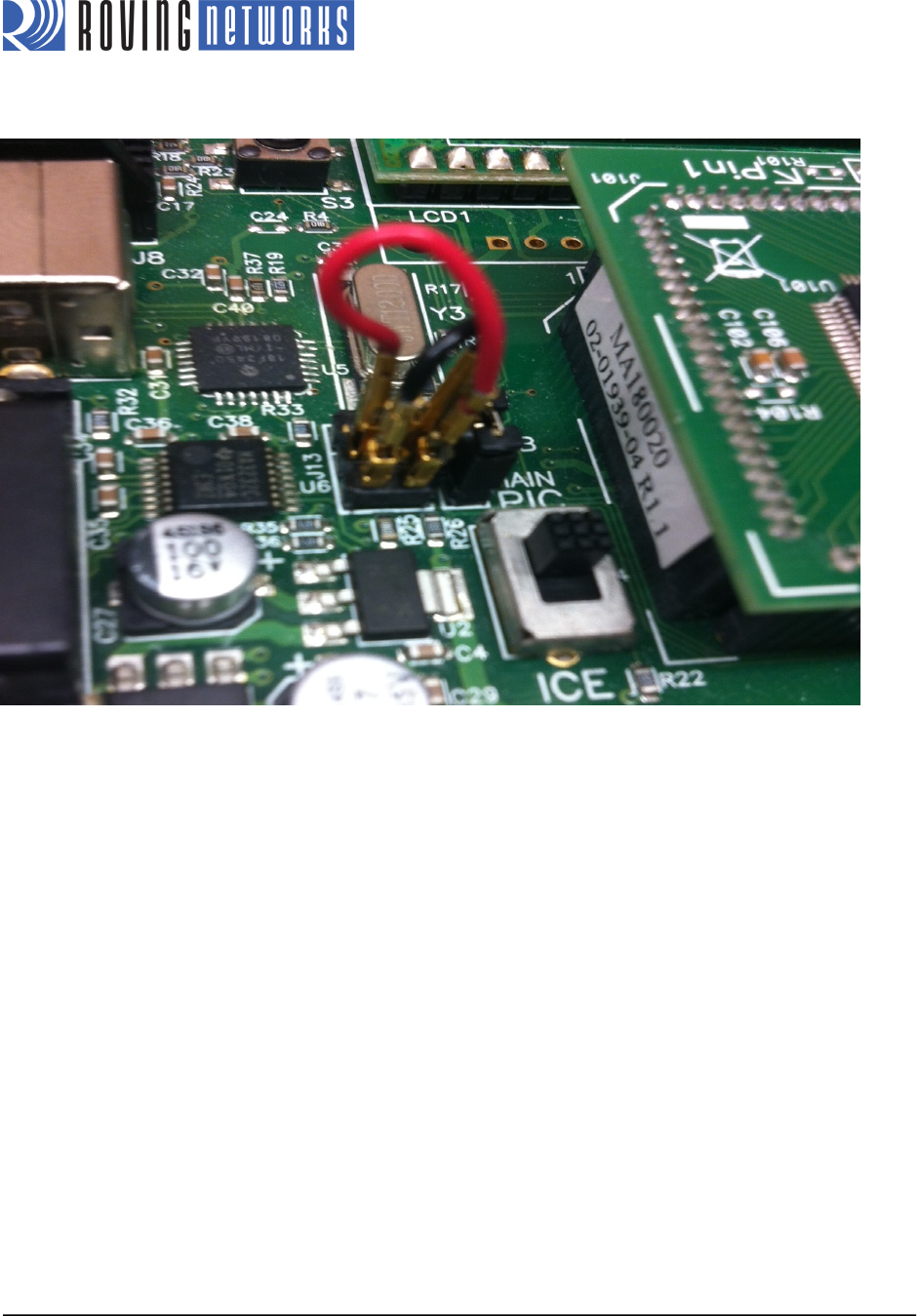
Figure 2. Jumper Selection for Command Mode Operation
!
3. Connect a serial cable from the PIC18 Explorer Board’s DE9 connector to the PC. If you are using a laptop that
does not have a serial connector, use a USB-to-serial converter cable to connect the serial cable to the laptop’s
USB port.
4. Connect the programmer to the PIC18 Explorer Board and apply power.
Program the PIC18F87J11 & Configure the RN-131/RN-171
In this step you configure the RN-131/RN-171 modules so that they automatically search for, and join, a preferred access
point. First, you use the following steps to program the PIC18F87J11 with software that allows the RN-131/RN-171 to be
configured for its current operating environment. These steps are specific to the PIC18 Explorer Board because of the way
in which the UARTs are connected on the board.
1. Using the MPLAB X IDE and the programmer, load the ConfigureInCmdMode.hex file into the PIC18F87J11.
This application performs two important tasks:
• It configures the PIC18F8i7J11 I/O pins appropriately.
• It allows the UART signal to traverse from the Explorer 18 board’s DE9 connector to the
RN-131-PICTAIL/RN-171-PICTAIL, temporarily bypassing the PIC (this step is specific to the PIC18 Explorer
Board).
2. Open your terminal emulator to the COM port of the PIC18 Explorer Board/RN-131-PICTAIL/RN-171-PICTAIL.
The serial port settings are 9600 baud, 8-bits data, no parity, 1-stop bit, and no flow control.