
User manual


!
www.rovingnetworks.com Version 1.1 9/20/2012 10
RN-131/171-PICTAIL-UM
SAMPLE APPLICATION DESIGN
This chapter provides a high-level overview of how the sample demo application was designed, and shows some of the
APIs you can use to communicate with RN-171 module.
Demo Application Flow Diagram
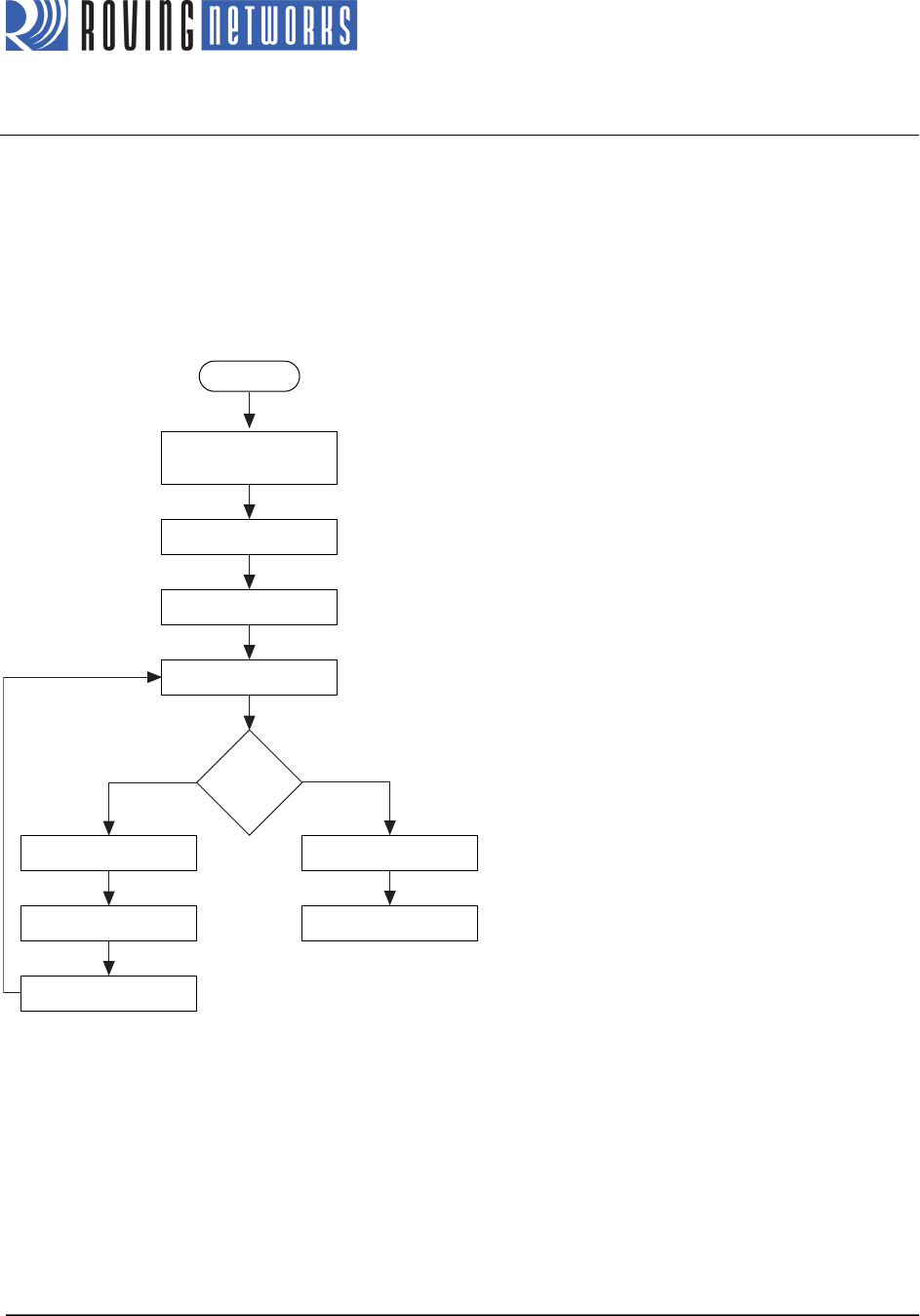
Figure 6 shows the demo application flow diagram.
Figure 6. Flow Diagram
!
Initialize the PIC18 Explorer Board Hardware
During this processing stage, the void BoardIint(void) API function performs the following tasks:
• Chooses the external 10-MHz crystal as the clock source.
• Configures the ports/pins as digital and selects their direction to match the functional requirements of the PICtail
connector.
• Turns off the LEDs.
• Clears the interrupt flags.
• Disables the peripheral interrupts.
Power Up
Initialize Explorer 18
Hardware
Initialize PIC18 UART
Reset RN-171 Module
Check RN-171 Status
Associated?
yesno
Set Command Mode
Congure & Save
Reboot
Enable RCV INT
Process Commands