
Datasheet


10/100 Non-PCI Ethernet Single Chip MAC + PHY
Datasheet
Revision 1.92 (06-27-11) 56 SMSC LAN91C111 REV C
DATASHEET
When this bit is cleared (0 - Default):
a. The internal PHY is enabled.
b. The external MII pins, including the MII Management interface pins are tri-stated.
Reserved – Reserved bits.
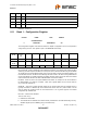
8.12 Bank 1 - Base Address Register
This register holds the I/O address decode option chosen for the LAN91C111. It is part of the EEPROM
saved setup and is not usually modified during run-time.
A15 - A13 and A9 - A5 - These bits are compared against the I/O address on the bus to determine
the IOBASE for the LAN91C111‘s registers. The 64k I/O space is fully decoded by the LAN91C111
down to a 16 location space, therefore the unspecified address lines A4, A10, A11 and A12 must be
all zeros.
All bits in this register are loaded from the serial EEPROM. The I/O base decode defaults to 300h
(namely, the high byte defaults to 18h).
Reserved – Reserved bits.
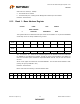
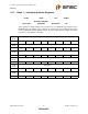
Below chart shows the decoding of I/O Base Address 300h:
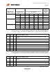
OFFSET NAME TYPE SYMBOL
2
BASE ADDRESS
REGISTER READ/WRITE BAR
HIGH
BYTE
A15A14A13A9A8A7A6A5
00011000
LOW
BYTE
Reserved Reserved
00000001
A15 A14 A13 A12 A11 A10 A9 A8 A7 A6 A5 A4 A3 A2 A1 A0
0000001100000000