
User manual


mTouch™ AR1100 User’s Guide
2011 Microchip Technology Inc. DS41604A-page 19
Chapter 3. Operation
3.1 CONFIGURATION
The AR1100 Touch Screen Controller Board is operational out of the box.
Communication protocol is detected automatically (as described below) and the
Mechanical mode jumper selects between 5-wire (jumper on) and 4/8-wire (jumper off).
If a USB cable is connected, the AR1100 Touch Screen Controller Board will default to
Mouse mode (HID-MOUSE). Additional configuration is possible (but generally, not
necessary) using commands described in the AR1100 IC data sheet. The Microchip AR
Configuration Utility Software can be used with the AR1100 Touch Screen Controller
Board to modify (fine tune) operational parameters, change the ‘default’ USB device or
actually update the control firmware. Any change made to the factory defaults is saved
to internal, nonvolatile memory.
3.2 COMMUNICATION
The AR1100 Touch Screen Controller Board supports both RS-232 and USB. The con-
troller will automatically detect and select between the two at power-up. The USB sup-
port is further defined to be one of three devices – HID-GENERIC, HID-MOUSE or
HID-DIGITIZER – the controller can be configured to power-up as any of the three
devices but the factory default is HID-MOUSE.
3.3 DATA FORMAT
The touch report data format for each communication protocol is defined below. The
HID-MOUSE and HID-DIGITIZER are compatible with intrinsic drivers of Windows
®
XP
and Windows 7, respectively. The HID-GENERIC and RS-232 protocols require
custom handling.
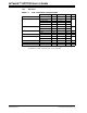
3.3.1 Mode: HID-GENERIC, RS-232
TABLE 3-1: TOUCH REPORT FORMAT – GENERIC
BYTE
BIT
7654321 0
1 1 RRR RRR P
2 0 X6 X5 X4 X3 X2 X1 X0
30 0X11X10X9X8X7X6
4 0 Y6 Y5 Y4 Y3 Y2 Y1 Y0
50 0Y11Y10Y9Y8Y7Y6
Note 1: P Pen state 1: Pen down; 0: Pen up
R (Reserved)
X X ordinate of touch location (12 bits)
Y Y ordinate of touch location (12 bits)