
User manual


mTouch™ AR1100 User’s Guide
DS41604A-page 14 2011 Microchip Technology Inc.
If the Microchip AR1100 Touch Screen Controller Board is installed into a monitor appli-
cation where the end user will decide to use USB communication or RS-232 commu-
nication, the board must be powered internally. Because the board cannot be supplied
with power from USB and internal 5V, it is recommended that the power (pin 1) contact
be removed from the USB socket to insure that multiple power source connections are
not permitted.
2.3 COMMUNICATION
The AR1100 Touch Screen Controller Board will automatically detect and configure
itself for the active communication protocol – RS-232 or USB HID. The controller will
default to RS-232 communication until USB activity is detected. Once the active
communication mode is determined, the inactive mode is decommissioned to minimize
power consumption. The active communication will remain in effect until power is
removed from the controller.
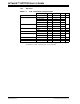
2.3.1 RS-232
Microchip cable harness p/n: C72-080S1F-09XDXF is a standard 6' long, round
shielded cable terminated by a DB-9 female connector and an 8-position single-row
socket. This cable has a ground termination wire running the length of the cable which
may be utilized to ground the controller board through the DB-9 connector. In any case,
for best performance, a jacketed, shielded cable is recommended.
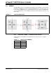
FIGURE 2-3: RS-232 CONNECTIONS
WARNING
SUPPLYING POWER FROM TWO DIFFERENT POWER SOURCES WILL
PERMANENTLY DESTROY YOUR CONTROLLER, YOUR COMPUTER, OR YOUR
MONITOR.