
User manual


mTouch™ AR1100 User’s Guide
2011 Microchip Technology Inc. DS41604A-page 13
Chapter 2. Connections
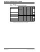
FIGURE 2-1: CONNECTIONS – OVERVIEW
2.1 MOUNTING
Two static ground mounting holes (0.122" diameter) are provided. Take special care to
insulate the controller from system and from EMI and RFI generating components of
the display. Use conductive 4-40 stand-offs or ground-lead wires terminated to the
grounded system enclosure or PC board to insure proper static protection and
grounding. STANDOFFS MUST NOT TOUCH ANY PORTION OF THE CIRCUIT.
Position the controller in a location that minimizes bending or creasing of the touch
screen overlay connection tail. Wear to the tail, printed traces, or tail header will
negatively impact touch screen performance.
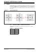
2.2 POWER
Power to the AR1100 Touch Screen Controller Board is provided by the H1
communication connector as seen in Figure 2-2. In USB Communication mode, power
can be derived from the USB bus. In RS-232 mode – regulated power (3.3V – 5.0V) is
provided from an external source. Check connections before applying power to the
controller as reversing polarity WILL damage the board.
FIGURE 2-2: POWER