
User manual


Hardware Specifications
© 2006 Microchip Technology Inc. DS51464C-page 101
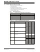
A.3.2 General Specifications
A.4 ICSP HARDWARE SPECIFICATIONS
This section covers:
• ICSP Header and Cable Pinout
•ICSP V
DD/VPP Operating Characteristics
• MPLAB PM3 Handler Operating Characteristics
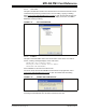
A.4.1 ICSP Header and Cable Pinout
MPLAB PM3 comes equipped with an ICSP pin header and cable. You can locate this
under where a socket module would be installed. The header configuration can be
found in Figure A-3 (viewed from above MPLAB PM3) and the cable color and signal
designations are listed in Table A-3.
FIGURE A-3: ICSP™ HEADER CONFIGURATION
TABLE A-2: GENERAL SPECIFICATIONS
Component Description
Power Supply 20.3W Dual Output +3.3VDC/5A, +5.0VDC/0.75A, w/ 5-pin Mini Din plug
USB Cable USB A-B M-M cable, 6 feet
Serial Cable RS-232 DB9 (1 end male, 1 end female)
ICSP™ Cable 18″ 15-pin, 22 AWG Super Flex Stranded Series 200 wire leads with
2 x 7 keyed housing
Pin Drivers 40 Universal pin drivers capable of supplying VDD, VPP, I/O, Ground
Diagnostics Power supply, CPU's, FPGA, CPLD
TABLE A-3: ICSP™ CABLE PINOUT
Pin Color Signal
1Violet CLK
2 Green PASS
3Orange DATA
4Brown FAIL
5 White LVP/Clock
6Blue GO
7Yellow VPP
8Yellow VPP
9Red VDD
10 White with blue stripe Test
11 Red VDD
12 Gray +5V
13 Black GND
14 Black GND