
Datasheet


© 2007-2012 Microchip Technology Inc. DS70292G-page 383
dsPIC33FJ32GP302/304, dsPIC33FJ64GPX02/X04, AND dsPIC33FJ128GPX02/X04
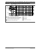
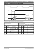
FIGURE 30-24: ADC CONVERSION (12-BIT MODE) TIMING CHARACTERISTICS
(ASAM = 0, SSRC<2:0> = 000)
AD55
TSAMP
Clear SAMPSet SAMP
AD61
ADCLK
Instruction
SAMP
AD60
DONE
AD1IF
1 2 3 4 5 6 87
1
– Software sets AD1CON. SAMP to start sampling.
2
– Sampling starts after discharge period. T
SAMP is described in
3
– Software clears AD1CON. SAMP to start conversion.
4
– Sampling ends, conversion sequence starts.
5
– Convert bit 11.
9
– One T
AD for end of conversion.
AD50
9
6
– Convert bit 10.
7
– Convert bit 1.
8
– Convert bit 0.
Execution
in the “dsPIC33F/PIC24H Family Reference Manual”.
Section 16. “Analog-to-Digital Converter (ADC)” (DS70183)