
Datasheet


dsPIC33FJ32GP302/304, dsPIC33FJ64GPX02/X04, AND dsPIC33FJ128GPX02/X04
DS70292G-page 380 © 2007-2012 Microchip Technology Inc.
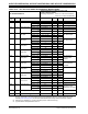
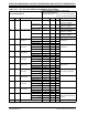
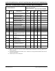
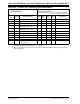
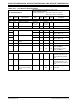
TABLE 30-41: ADC MODULE SPECIFICATIONS
AC CHARACTERISTICS
Standard Operating Conditions: 3.0V to 3.6V
(unless otherwise stated)
Operating temperature -40°C ≤ T
A ≤ +85°C for Industrial
-40°C ≤T
A ≤+125°C for Extended
Param
No.
Symbol Characteristic Min. Typ Max. Units Conditions
Device Supply
AD01 AV
DD Module VDD Supply Greater of
VDD – 0.3
or 3.0
— Lesser of
VDD + 0.3
or 3.6
V
—
AD02 AVSS Module VSS Supply VSS – 0.3 — VSS + 0.3 V —
Reference Inputs
AD05 V
REFH Reference Voltage High AVSS + 2.5 — AVDD V
AD05a 3.0 — 3.6 V VREFH = AVDD
VREFL = AVSS = 0
AD06 V
REFL Reference Voltage Low AVSS —AVDD – 2.5 V
AD06a 0 — 0 V VREFH = AVDD
VREFL = AVSS = 0
AD07 V
REF Absolute Reference
Voltage
2.5 — 3.6 V VREF = VREFH - VREFL
AD08 IREF Current Drain — — 10 μA ADC off
AD09 I
AD Operating Current —
—
7.0
2.7
9.0
3.2
mA
mA
ADC operating in 10-bit
mode, see Note 1
ADC operating in 12-bit
mode, see Note 1
Analog Input
AD12 VINH Input Voltage Range VINH VINL —VREFH V This voltage reflects Sample
and Hold Channels 0, 1, 2,
and 3 (CH0-CH3), positive
input
AD13 VINL Input Voltage Range VINL VREFL —AVSS + 1V V This voltage reflects Sample
and Hold Channels 0, 1, 2,
and 3 (CH0-CH3), negative
input
AD17 R
IN Recommended Imped-
ance of Analog Voltage
Source
—
—
—
—
200
200
Ω
Ω
10-bit ADC
12-bit ADC
Note 1: These parameters are not characterized or tested in manufacturing.