
Datasheet


© 2007-2012 Microchip Technology Inc. DS70292G-page 317
dsPIC33FJ32GP302/304, dsPIC33FJ64GPX02/X04, AND dsPIC33FJ128GPX02/X04
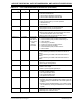
RSS<1:0>
(1)
FSS
(1)
Immediate Secure Segment RAM Code Protection
11 = No Secure RAM defined
10 = Secure RAM is 256 Bytes less BS RAM
01 = Secure RAM is 2048 Bytes less BS RAM
00 = Secure RAM is 4096 Bytes less BS RAM
GSS<1:0> FGS Immediate General Segment Code-Protect bit
11 = User program memory is not code-protected
10 = Standard security
0x
= High security
GWRP FGS Immediate General Segment Write-Protect bit
1 = User program memory is not write-protected
0 = User program memory is write-protected
IESO FOSCSEL Immediate Two-speed Oscillator Start-up Enable bit
1 = Start-up device with FRC, then automatically switch to the
user-selected oscillator source when ready
0 = Start-up device with user-selected oscillator source
FNOSC<2:0> FOSCSEL If clock switch
is enabled,
RTSP effect is
on any device
Reset;
otherwise,
Immediate
Initial Oscillator Source Selection bits
111 = Internal Fast RC (FRC) oscillator with postscaler
110 = Internal Fast RC (FRC) oscillator with divide-by-16
101 = LPRC oscillator
100 = Secondary (LP) oscillator
011 = Primary (XT, HS, EC) oscillator with PLL
010 = Primary (XT, HS, EC) oscillator
001 = Internal Fast RC (FRC) oscillator with PLL
000 = FRC oscillator
FCKSM<1:0> FOSC Immediate Clock Switching Mode bits
1x = Clock switching is disabled, Fail-Safe Clock Monitor is
disabled
01 = Clock switching is enabled, Fail-Safe Clock Monitor is
disabled
00 = Clock switching is enabled, Fail-Safe Clock Monitor is
enabled
IOL1WAY FOSC Immediate Peripheral pin select configuration
1 = Allow only one reconfiguration
0 = Allow multiple reconfigurations
OSCIOFNC FOSC Immediate OSC2 Pin Function bit (except in XT and HS modes)
1 = OSC2 is clock output
0 = OSC2 is general purpose digital I/O pin
POSCMD<1:0> FOSC Immediate Primary Oscillator Mode Select bits
11 = Primary oscillator disabled
10 = HS Crystal Oscillator mode
01 = XT Crystal Oscillator mode
00 = EC (External Clock) mode
FWDTEN FWDT Immediate Watchdog Timer Enable bit
1 = Watchdog Timer always enabled (LPRC oscillator cannot be
disabled. Clearing the SWDTEN bit in the RCON register has
no effect.)
0 = Watchdog Timer enabled/disabled by user software (LPRC
can be disabled by clearing the SWDTEN bit in the RCON
register)
WINDIS FWDT Immediate Watchdog Timer Window Enable bit
1 = Watchdog Timer in Non-Window mode
0 = Watchdog Timer in Window mode
TABLE 27-2: dsPIC CONFIGURATION BITS DESCRIPTION (CONTINUED)
Bit Field Register RTSP Effect Description
Note 1: This Configuration register is not available on dsPIC33FJ32GP302/304 devices.