
Datasheet


dsPIC33FJ32GP302/304, dsPIC33FJ64GPX02/X04, AND dsPIC33FJ128GPX02/X04
DS70292G-page 310 © 2007-2012 Microchip Technology Inc.
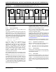
bit 2 BEP: Byte Enable Polarity bit
1 = Byte enable active-high (PMBE)
0 = Byte enable active-low (PMBE
)
bit 1 WRSP: Write Strobe Polarity bit
For Slave modes and Master mode 2 (PMMODE<9:8> = 00,01,10):
1 = Write strobe active-high (PMWR)
0 = Write strobe active-low (PMWR
)
For Master mode 1 (PMMODE<9:8> = 11):
1 = Enable strobe active-high (PMENB)
0 = Enable strobe active-low (PMENB)
bit 0 RDSP: Read Strobe Polarity bit
For Slave modes and Master mode 2 (PMMODE<9:8> = 00,01,10):
1 = Read strobe active-high (PMRD)
0 = Read strobe active-low (PMRD)
For Master mode 1 (PMMODE<9:8> =
11):
1 = Read/write strobe active-high (PMRD/PMWR)
0 = Read/write strobe active-low (PMRD/PMWR)
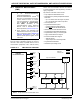
REGISTER 26-1: PMCON: PARALLEL MASTER PORT CONTROL REGISTER (CONTINUED)
Note 1: These bits have no effect when their corresponding pins are used as address lines.