
Datasheet


dsPIC33FJ32GP302/304, dsPIC33FJ64GPX02/X04, AND dsPIC33FJ128GPX02/X04
DS70292G-page 304 © 2007-2012 Microchip Technology Inc.
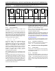
25.5 Programmable CRC Registers
REGISTER 25-1: CRCCON: CRC CONTROL REGISTER
U-0 U-0 R/W-0 R-0 R-0 R-0 R-0 R-0
— — CSIDL VWORD<4:0>
bit 15 bit 8
R-0 R-1 U-0 R/W-0 R/W-0 R/W-0 R/W-0 R/W-0
CRCFUL CRCMPT
— CRCGO PLEN<3:0>
bit 7 bit 0
Legend:
R = Readable bit W = Writable bit U = Unimplemented bit, read as ‘0’
-n = Value at POR ‘1’ = Bit is set ‘0’ = Bit is cleared x = Bit is unknown
bit 15-14 Unimplemented: Read as ‘0’
bit 13 CSIDL: CRC Stop in Idle Mode bit
1 = Discontinue module operation when device enters Idle mode
0 = Continue module operation in Idle mode
bit 12-8 VWORD<4:0>: Pointer Value bits
Indicates the number of valid words in the FIFO. Has a maximum value of 8 when PLEN<3:0> is
greater than 7, or 16 when PLEN<3:0> is less than or equal to 7.
bit 7 CRCFUL: FIFO Full bit
1 = FIFO is full
0 = FIFO is not full
bit 6 CRCMPT: FIFO Empty bit
1 = FIFO is empty
0 = FIFO is not empty
bit 5 Unimplemented: Read as ‘0’
bit 4 CRCGO: Start CRC bit
1 = Start CRC serial shifter
0 = Turn off CRC serial shifter after FIFO is empty
bit 3-0 PLEN<3:0>: Polynomial Length bits
Denotes the length of the polynomial to be generated minus 1.