
Datasheet


dsPIC33FJ32GP302/304, dsPIC33FJ64GPX02/X04, AND dsPIC33FJ128GPX02/X04
DS70292G-page 266 © 2007-2012 Microchip Technology Inc.
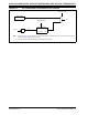
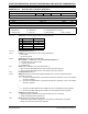
FIGURE 21-3: ADC CONVERSION CLOCK PERIOD BLOCK DIAGRAM
1
0
ADC Internal
RC Clock
(2)
T
OSC
(1)
X2
ADC Conversion
Clock Multiplier
1, 2, 3, 4, 5,..., 64
AD1CON3<15>
TCY
TAD
6
AD1CON3<5:0>
Note 1: Refer to Figure 9-2 for the derivation of Fosc when the PLL is enabled. If the PLL is not used, Fosc is equal to
the clock source frequency. Tosc = 1/Fosc.
2: See the ADC electrical characteristics for the exact RC clock value.