
Datasheet


© 2007-2012 Microchip Technology Inc. DS70292G-page 227
dsPIC33FJ32GP302/304, dsPIC33FJ64GPX02/X04, AND dsPIC33FJ128GPX02/X04
19.0 ENHANCED CAN (ECAN™)
MODULE
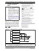
19.1 Overview
The Enhanced Controller Area Network (ECAN™)
module is a serial interface, useful for communicating
with other CAN modules or microcontroller devices.
This interface/protocol was designed to allow commu-
nications within noisy environments. The
dsPIC33FJ32GP302/304, dsPIC33FJ64GPX02/X04,
and dsPIC33FJ128GPX02/X04 devices contain up to
two ECAN modules.
The ECAN module is a communication controller
implementing the CAN 2.0 A/B protocol, as defined in
the BOSCH CAN specification. The module supports
CAN 1.2, CAN 2.0A, CAN 2.0B Passive and CAN 2.0B
Active versions of the protocol. The module implemen-
tation is a full CAN system. The CAN specification is
not covered within this data sheet. The reader can refer
to the BOSCH CAN specification for further details.
The module features are as follows:
• Implementation of the CAN protocol, CAN 1.2,
CAN 2.0A and CAN 2.0B
• Standard and extended data frames
• 0-8 bytes data length
• Programmable bit rate up to 1 Mbit/sec
• Automatic response to remote transmission
requests
• Up to eight transmit buffers with application speci-
fied prioritization and abort capability (each buffer
can contain up to 8 bytes of data)
• Up to 32 receive buffers (each buffer can contain up
to 8 bytes of data)
• Up to 16 full (standard/extended identifier)
acceptance filters
• Three full acceptance filter masks
• DeviceNet™ addressing support
• Programmable wake-up functionality with integrated
low-pass filter
• Programmable Loopback mode supports self-test
operation
• Signaling via interrupt capabilities for all CAN
receiver and transmitter error states
• Programmable clock source
• Programmable link to input capture module (IC2 for
CAN1) for time-stamping and network synchroniza-
tion
• Low-power Sleep and Idle mode
The CAN bus module consists of a protocol engine and
message buffering/control. The CAN protocol engine
handles all functions for receiving and transmitting
messages on the CAN bus. Messages are transmitted
by first loading the appropriate data registers. Status
and errors can be checked by reading the appropriate
registers. Any message detected on the CAN bus is
checked for errors and then matched against filters to
see if it should be received and stored in one of the
receive registers.
Note 1: This data sheet summarizes the features
of the dsPIC33FJ32GP302/304,
dsPIC33FJ64GPX02/X04, and
dsPIC33FJ128GPX02/X04 families of
devices. It is not intended to be a compre-
hensive reference source. To comple-
ment the information in this data sheet,
refer to Section 21. “Enhanced Control-
ler Area Network (ECAN™)” (DS70185)
of the “dsPIC33F/PIC24H Family Refer-
ence Manual”, which is available from the
Microchip website (www.microchip.com).
2: Some registers and associated bits
described in this section may not be avail-
able on all devices. Refer to Section 4.0
“Memory Organization” in this data
sheet for device-specific register and bit
information.