
Datasheet


© 2007-2012 Microchip Technology Inc. DS70292G-page 223
dsPIC33FJ32GP302/304, dsPIC33FJ64GPX02/X04, AND dsPIC33FJ128GPX02/X04
18.3 UART Control Registers
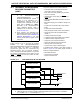
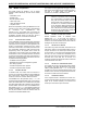
REGISTER 18-1: UxMODE: UARTx MODE REGISTER
R/W-0 U-0 R/W-0 R/W-0 R/W-0 U-0 R/W-0 R/W-0
UARTEN
(1)
— USIDL IREN
(2)
RTSMD —UEN<1:0>
bit 15 bit 8
R/W-0 HC R/W-0 R/W-0 HC R/W-0 R/W-0 R/W-0 R/W-0 R/W-0
WAKE LPBACK ABAUD URXINV BRGH PDSEL<1:0> STSEL
bit 7 bit 0
Legend: HC = Hardware cleared
R = Readable bit W = Writable bit U = Unimplemented bit, read as ‘0’
-n = Value at POR ‘1’ = Bit is set ‘0’ = Bit is cleared x = Bit is unknown
bit 15 UARTEN: UARTx Enable bit
(1)
1 = UARTx is enabled; all UARTx pins are controlled by UARTx as defined by UEN<1:0>
0 = UARTx is disabled; all UARTx pins are controlled by port latches; UARTx power consumption
minimal
bit 14 Unimplemented: Read as ‘0’
bit 13 USIDL: Stop in Idle Mode bit
1 = Discontinue module operation when device enters Idle mode
0 = Continue module operation in Idle mode
bit 12 IREN: IrDA
®
Encoder and Decoder Enable bit
(2)
1 =IrDA
®
encoder and decoder enabled
0 =IrDA
®
encoder and decoder disabled
bit 11 RTSMD: Mode Selection for UxRTS Pin bit
1 =UxRTS pin in Simplex mode
0 =UxRTS
pin in Flow Control mode
bit 10 Unimplemented: Read as ‘0’
bit 9-8 UEN<1:0>: UARTx Enable bits
11 = UxTX, UxRX and BCLK pins are enabled and used; UxCTS
pin controlled by port latches
10 = UxTX, UxRX, UxCTS and UxRTS pins are enabled and used
01 = UxTX, UxRX and UxRTS
pins are enabled and used; UxCTS pin controlled by port latches
00 = UxTX and UxRX pins are enabled and used; UxCTS
and UxRTS/BCLK pins controlled by
port latches
bit 7 WAKE: Wake-up on Start bit Detect During Sleep Mode Enable bit
1 = UARTx continues to sample the UxRX pin; interrupt generated on falling edge; bit cleared
in hardware on following rising edge
0 = No wake-up enabled
bit 6 LPBACK: UARTx Loopback Mode Select bit
1 = Enable Loopback mode
0 = Loopback mode is disabled
bit 5 ABAUD: Auto-Baud Enable bit
1 = Enable baud rate measurement on the next character – requires reception of a Sync field (55h)
before other data; cleared in hardware upon completion
0 = Baud rate measurement disabled or completed
Note 1: Refer to Section 17. “UART” (DS70188) in the “dsPIC33F/PIC24H Family Reference Manual” for
information on enabling the UART module for receive or transmit operation.
2: This feature is only available for the 16x BRG mode (BRGH = 0).