
Datasheet


dsPIC33FJ32GP302/304, dsPIC33FJ64GPX02/X04, AND dsPIC33FJ128GPX02/X04
DS70292G-page 130 © 2007-2012 Microchip Technology Inc.
The DMA controller features eight identical data
transfer channels.
Each channel has its own set of control and status
registers. Each DMA channel can be configured to
copy data either from buffers stored in dual port DMA
RAM to peripheral SFRs, or from peripheral SFRs to
buffers in DMA RAM.
The DMA controller supports the following features:
• Eight DMA channels
• Register Indirect With Post-increment Addressing
mode
• Register Indirect Without Post-increment
Addressing mode
• Peripheral Indirect Addressing mode (peripheral
generates destination address)
• CPU interrupt after half or full block transfer
complete
• Byte or word transfers
• Fixed priority channel arbitration
• Manual (software) or Automatic (peripheral DMA
requests) transfer initiation
• One-Shot or Auto-Repeat block transfer modes
• Ping-Pong mode (automatic switch between two
DPSRAM start addresses after each block trans-
fer complete)
• DMA request for each channel can be selected
from any supported interrupt source
• Debug support features
For each DMA channel, a DMA interrupt request is
generated when a block transfer is complete.
Alternatively, an interrupt can be generated when half of
the block has been filled.
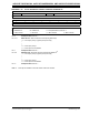
FIGURE 8-1: TOP LEVEL SYSTEM ARCHITECTURE USING A DEDICATED TRANSACTION BUS
CPU
SRAM
DMA RAM
CPU Peripheral DS Bus
Peripheral 3
DMA
Peripheral
Non-DMA
SRAM X-Bus
PORT 2
PORT 1
Peripheral 1
DMA
Ready
Peripheral 2
DMA
Ready
Ready
Ready
DMA DS Bus
CPU DMA
CPU DMA
CPU DMA
Peripheral Indirect Address
DMA
Control
DMA Controller
DMA
Channels
Note: CPU and DMA address buses are not shown for clarity.