
Information

dsPIC33FJ32GP302/304, dsPIC33FJ64GPX02/X04 and dsPIC33FJ128GPX02/X04
DS80000443K-page 6 2009-2013 Microchip Technology Inc.
6. Module: I
2
C
If there are two I
2
C devices on the bus, one of
them is acting as the master receiver and the other
as the slave transmitter. If both devices are
configured for 10-Bit Addressing mode, and have
the same value in the A10 and A9 bits of their
addresses, then when the slave select address is
sent from the master, both the master and slave
Acknowledge it. When the master sends out the
read operation, both the master and the slave
enter into Read mode and both of them transmit
the data. The resultant data will be the ANDing of
the two transmissions.
Work around
In all I
2
C devices, the addresses, as well as bits,
A10 and A9, should be different.
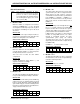
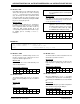
Affected Silicon Revisions
7. Module: I
2
C
When the I
2
C module is configured as a 10-bit
slave with an address of 0x02, the I2CxRCV
register content for the lower address byte is 0x01
rather than 0x02; however, the module
Acknowledges both address bytes.
Work around
None.
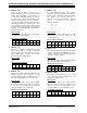
Affected Silicon Revisions
8. Module: I
2
C
With the I
2
C module enabled, the PORT bits and
external interrupt input functions (if any)
associated with the SCLx and SDAx pins do not
reflect the actual digital logic levels on the pins.
Work around
If the SDAx and/or SCLx pins need to be polled,
these pins should be connected to other port pins
in order to be read correctly. This issue does not
affect the operation of the I
2
C module.
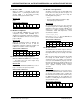
Affected Silicon Revisions
9. Module: I
2
C
In 10-Bit Addressing mode, some address
matches do not set the RBF flag or load the I2Cx
Receive register, I2CxRCV, if the lower address
byte matches the reserved addresses. In
particular, these include all addresses with the
form, ‘xx0000xxxx’ and ‘xx1111xxxx’, with the
following exceptions:
• 001111000x
• 011111001x
• 101111010x
• 111111011x
Work around
Ensure that the lower address byte in 10-Bit
Addressing mode does not match any 7-bit
reserved addresses.
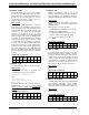
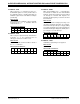
Affected Silicon Revisions
10. Module: I
2
C
When the I
2
C module is operating in either Master
or Slave mode, after the ACKSTAT bit is set when
receiving a NACK, it may be cleared by the
reception of a Start or Stop bit.
Work around
Store the value of the ACKSTAT bit immediately
after receiving a NACK from the master.
Affected Silicon Revisions
11. Module: UART
The UARTx error interrupt may not occur, or may
occur at an incorrect time, if multiple errors occur
during a short period of time.
Work around
Read the error flags in the UxSTA register
whenever a byte is received to verify the error
status. In most cases, these bits will be correct,
even if the UARTx error interrupt fails to occur.
Affected Silicon Revisions
A1 A2 A3 A4 A5
XXXX
X
A1 A2 A3 A4
A5
XXXX
X
A1 A2 A3 A4
A5
XXXX
X
A1 A2 A3 A4 A5
XXXX
X
A1 A2 A3 A4 A5
XXXX
X
A1 A2 A3 A4
A5
XXXX
X