
Datasheet


dsPIC33FJ32MC202/204 and dsPIC33FJ16MC304
DS70283K-page 236 © 2007-2012 Microchip Technology Inc.
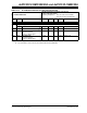
TABLE 24-7: DC CHARACTERISTICS: POWER-DOWN CURRENT (IPD)
DC CHARACTERISTICS
Standard Operating Conditions: 3.0V to 3.6V
(unless otherwise stated)
Operating temperature -40°C ≤ TA ≤ +85°C for Industrial
-40°C ≤ TA ≤ +125°C for Extended
Parameter
No.
(3)
Typical
(2)
Max Units Conditions
Power-Down Current (IPD)
(1)
DC60d 55 500 μA -40°C
3.3V Base Power-Down Current
(3,4)
DC60a 63 300 μA +25°C
DC60b 85 350 μA +85°C
DC60c 146 600 μA +125°C
DC61d 8 15 μA -40°C
3.3V Watchdog Timer Current: ΔI
WDT
(3,5)
DC61a 2 3 μA +25°C
DC61b 2 2 μA +85°C
DC61c 3 5 μA +125°C
Note 1: I
PD (Sleep) current is measured as follows:
• CPU core is off, oscillator is configured in EC mode and external clock active, OSC1 is driven with
external square wave from rail-to-rail (EC clock overshoot/undershoot < 250 mV required)
• CLKO is configured as an I/O input pin in the Configuration word
• All I/O pins are configured as inputs and pulled to V
SS
•MCLR = VDD, WDT and FSCM are disabled, all peripheral modules are disabled (PMDx bits are all
ones)
• VREGS bit (RCON<8>) = 0 (i.e., core regulator is set to stand-by while the device is in Sleep mode)
• RTCC is disabled.
• JTAG is disabled
2: Data in the “Typ” column is at 3.3V, +25ºC unless otherwise stated.
3: The Watchdog Timer Current is the additional current consumed when the WDT module is enabled. This
current should be added to the base I
PD current.
4: These currents are measured on the device containing the most memory in this family.
5: These parameters are characterized, but are not tested in manufacturing.