
Datasheet


© 2007-2012 Microchip Technology Inc. DS70283K-page 101
dsPIC33FJ32MC202/204 and dsPIC33FJ16MC304
8.0 OSCILLATOR
CONFIGURATION
The oscillator system for dsPIC33FJ32MC202/204 and
dsPIC33FJ16MC304 devices provides:
• External and internal oscillator options as clock
sources.
• An on-chip Phase-Locked Loop (PLL) to scale the
internal operating frequency to the required
system clock frequency.
• An internal FRC oscillator that can also be used
with the PLL, thereby allowing full-speed
operation without any external clock generation
hardware.
• Clock switching between various clock sources.
• Programmable clock postscaler for system power
savings.
• A Fail-Safe Clock Monitor (FSCM) that detects
clock failure and takes fail-safe measures.
• A Clock Control register (OSCCON).
• Nonvolatile Configuration bits for main oscillator
selection.
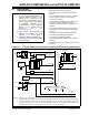
A simplified diagram of the oscillator system is shown
in Figure 8-1.
FIGURE 8-1: dsPIC33FJ32MC202/204 and dsPIC33FJ16MC304 OSCILLATOR SYSTEM DIAGRAM
Note 1: This data sheet summarizes the features
of the dsPIC33FJ32MC202/204 and
dsPIC33FJ16MC304 devices. It is not
intended to be a comprehensive refer-
ence source. To complement the infor-
mation in this data sheet, refer to Section
7. “Oscillator” (DS70186) of the
dsPIC33F/PIC24H Family Reference
Manual”, which is available from the
Microchip web site
(www.microchip.com).
2: Some registers and associated bits
described in this section may not be
available on all devices. Refer to
Section 4.0 “Memory Organization” in
this data sheet for device-specific register
and bit information.
Note 1: See Figure 8-2 for PLL details.
2: If the Oscillator is used with XT or HS modes, an external parallel resistor with the value of 1 MΩ must be connected.
3: The term
FP refers to the clock source for all of the peripherals, while FCY refers to the clock source for the CPU.
Throughout this document,
FCY and FP are used interchangeably, except in the case of DOZE mode. FP and FCY will
be different when DOZE mode is used with any ratio other than 1:1 which is the default.
Secondary Oscillator (SOSC)
LPOSCEN
SOSCO
Timer 1
XTPLL, HSPLL,
XT, HS, EC
FRCDIV<2:0>
WDT, PWRT,
FSCM
FRCDIVN
SOSC
FRCDIV16
ECPLL, FRCPLL
NOSC<2:0> FNOSC<2:0>
Reset
FRC
Oscillator
LPRC
Oscillator
DOZE<2:0>
S3
S1
S2
S1/S3
S7
S6
FRC
LPRC
S0
S5
S4
÷16
Clock Switch
S7
Clock Fail
÷
2
TUN<5:0>
PLL
(1)
FCY
(3)
FOSC
FRCDIV
DOZE
OSC2
OSC1
Primary Oscillator (P
OSC)
R
(2)
POSCMD<1:0>
FP
(3)
SOSCI