
Information


dsPIC33FJ06GS101/X02 and dsPIC33FJ16GSX02/X04
DS80000439N-page 8 2009-2013 Microchip Technology Inc.
15. Module: UART
When the UART is configured for IR interface
operations (UxMODE<9:8> = 11), the 16x baud
clock signal on the BCLK pin is present only when
the module is transmitting. The pin is idle at all
other times.
Work around
Configure one of the output compare modules to
generate the required baud clock signal when the
UART is receiving data or in an Idle state.
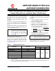
Affected Silicon Revisions
16. Module: I
2
C™
If there are two I
2
C devices on the bus, one of
them is acting as the Master receiver and the other
as the Slave transmitter. If both devices are
configured for 10-bit addressing mode, and have
the same value in the A10 and A9 bits of their
addresses, then when the Slave select address is
sent from the Master, both the Master and Slave
Acknowledge it. When the Master sends out the
read operation, both the Master and the Slave
enter into Read mode and both of them transmit
the data. The resultant data will be the ANDing of
the two transmissions.
Work around
In all I
2
C devices, the addresses, as well as bits A10
and A9, should be different.
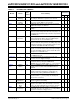
Affected Silicon Revisions
17. Module: PWM
When the primary or secondary PWMx generator
is selected as a trigger source for ADC convert
pairs 3, 4, 5 or 6 and the PWM module is running
at the maximum speed, the PWM module may fail
to trigger a conversion on these ADC pairs.
Work arounds
Work around 1:
Configure the PWM module to trigger the ADC
module per the following steps (see Example 1 for
the code used in this work around):
1. Enable the dual trigger mode bit (DTM) in the
TRGCONx register.
2. Configure the TRIGx register to the desired
trigger point.
3. Configure the STRIGx register to TRIGx + 0x8.
4. Select the PWMx primary trigger as the ADC
trigger source for conversion.
If the PWM channel is configured for independent
output mode and both channels are operating on
the same time base, the phase difference between
the two channels must be considered when setting
the STRIGx register. This work around will not
work for True Independent Time Base mode.
With this work around, the PWMx secondary
trigger should not be selected as the trigger source
for the ADC convert pair.
Work around 2:
Configure the PWM Input Clock Prescaler bits
(PCLKDIV) for divide by 2 or higher.
Work around 3:
Utilize other available trigger sources, such as
software or timer triggers, to initiate conversion on
the affected ADC convert pairs.
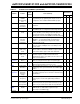
Affected Silicon Revisions
EXAMPLE 1: USING DUAL TRIGGER MODE
A2 A3 A4
XX
X
A2 A3
A4
XX
X
A2 A3 A4
X
TRGCON1bits.DTM = 1; /* Dual trigger mode (DTM) and STRIG used in combination to generate */
/* ADCPx triggers */
TRIG1 = 1224; /* Configure desired trigger */
STRIG1 = 1232; /* STRIG1 should be configured for TRIG1 + 8 */
ADCPC2bits.TRGSRC5 = 0x4; /* PWM1 primary trigger selected as ADC trigger source for ADCP5*/