
Information


2009-2013 Microchip Technology Inc. DS80000439N-page 3
dsPIC33FJ06GS101/X02 and dsPIC33FJ16GSX02/X04
Core PGEC3/
PGED3
Programming
Pins
18. When using the PGEC3/PGED3 pins for device
programming, the programming time may be slower as
compared to other available PGECx/PGEDx pin pairs.
XXX
UART Break
Character
Generation
19. The UART module will not generate back-to-back Break
characters.
XXX
PWM Current Limit 20. Cycle-by-cycle current-limit operation does not work when
the PWM module is configured for Center-Aligned mode.
XXX
PWM Current Reset
Mode
21. Current Reset mode does not work when the current-limit
source (CLSRC) occurs during, and persists past, the
assertive time interval of the PWM, and leading-edge
blanking time is less than the PWM assertive time interval.
XXX
UART IrDA
®
Encoder/
Decoder
(8-bit Mode)
22. When the UART module is operating in 8-bit mode
(PDSEL = 0x) and using the IrDA encoder/decoder
(IREN = 1), the module incorrectly transmits a data
payload of 80h as 00h.
XXX
UART UxE Interrupt 23. The UART error interrupt may not occur, or may occur at
an incorrect time, if multiple errors occur during a short
period of time.
XXX
I
2
C 10-Bit
Addressing
Mode
24. When the I
2
C™ module is configured as a 10-bit slave
with an address of 0x102, the I2CxRCV register content
for the lower address byte is 0x01 rather than 0x02.
XXX
I
2
C 10-Bit
Addressing
Mode
25. The 10-bit slave does not set the RBF flag or load the
I2CxRCV register, on address match if the Least
Significant bits (LSbs) of the address are the same as the
7-bit reserved addresses.
XXX
PSV
Operations
Addressing
Modes
26. An address error trap occurs in certain addressing modes
when accessing the first four bytes of any PSV page.
XXX
Comparator Sleep Mode 27. The Comparator fails to wake the CPU from Sleep mode
when the internal voltage reference is used.
XXX
PWM Independent
Time Base
28. When updating the frequency on the fly, push-pull PWM
outputs may not be synchronized with other PWM output
modes.
XXX
Analog
Comparator
Internal
Band Gap
Reference
Voltage
29. The Internal Band Gap Reference Voltage (INTREF) for
the analog comparator does not meet the stated accuracy
specifications.
XXX
Auxiliary PLL Input
Frequency
30. For extended temperature devices, the auxiliary PLL input
frequency does not meet the published specification
range.
XXX
ADC Current
Consumption
in Sleep Mode
31. If the ADC module is in an enabled state when the device
enters Sleep mode, the power-down current (I
PD) of the
device may exceed the device data sheet specifications.
XXX
High-Speed
PWM
PWM Module
Enable
32. A glitch may be observed on the PWM pins when the
PWM module is enabled after assignment of pin
ownership to the PWM module.
XXX
Reserved — 33. ——
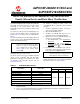
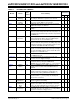
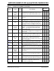
TABLE 2: SILICON ISSUE SUMMARY (CONTINUED)
Module Feature
Item
Number
Issue Summary
Affected
Revisions
(1)
A2 A3 A4
Note 1: Only those issues indicated in the last column apply to the current silicon revision.