
Information


5
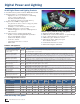
16-bit Embedded Control Solutions
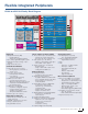
Flexible Integrated Peripherals
Digital I/O
■ Peripheral Pin Select (PPS)
• Remap digital I/O
• Supports most digital peripherals
■ Up to 122 programmable digital I/O pins
■ Wake-up/Interrupt-on-change on up to
52 pins
■ High current sink/source
Communication Modules
■ 3-wire SPI: up to three modules
• Framing supports I/O interface to
simple codecs
■ I²C™: up to three modules
• Full multi-master and slave
mode support
• 7-bit and 10-bit addressing
■ UART: up to four modules
• Interrupt-on-address bit detect
• Wake-up on Start bit from Sleep mode
• 4-character TX and RX FIFO buffers
• LIN and IrDA support
■ USB Device, Host and OTG
• Internal Boost Regulator requires
minimal external components
• Separate 3.3V regulator
• Transparent RAM buffer interface
■ CAN 2.0 (up to two modules)
Digital Power Peripherals
■ 10-bit ADC up to 4 Msps, Up to six
sample and holds
■ PS PWM, 1 nS duty cycle resolution
■ Analog comparators, 25 ns
■ Programmable reference
Timers/Capture/Compare/PWM
■ Timer/counters: up to nine 16-bit timers
• Can pair up to make 32-bit timers
• One timer can run as real-time clock
■ Input capture: up to 16 channels
• Capture on rising, falling or both edges
• 4-deep FIFO on each capture
■ Output compare: up to 16 channels
• Dedicated timer
• Single or dual 16-bit compare mode
• 16-bit glitchless PWM m
ode
Auxilary Functions
■ LCD Segment Driver:
• 60 Segment × 8 Common Driver
■ Graphics Controller Features:
• 3× graphics hardware acceleration units
• Color look-up table with up to 256 entries
• Direct interface to monochrome,
C-STN, TFT, OLED
■ Parallel Master Slave Port (PMP/PSP):
• Communicates with external
data memory, communications
peripherals, LCDs
• Supports 8-bit or 16-bit data
• Supports 16 address lines
■ Hardware Real-Time Clock/Calendar (RTCC):
• Provides clock, calendar and
alarm functions
■ Programmable CRC generator
■ Charge time measurement unit (CTMU)
• Capacitive touch sense keypad I/F
• Provides 1 ns resolution time
measurements
• Temperature sensing
■ Peripheral Trigger Generator (PTG)
Analog Subsystems
■ On-chip high-speed op amps
• Up to 10 MHz gain bandwidth
■ Analog comparators (up to 4):
• Programmable reference
■ DAC
■ ADC
• 10-bit up to 1.1 Msps, 4 S&H
• 12-bit up to 1 Msps
• 16-bit Sigma Delta ADC, two
channels
• Buffered outputor DMA
• Autoscanning
• Supports CVD touch
Motor Control Peripherals
■ Motor Control PWM: up to 14 outputs
• Up to seven duty cycle generators
• Independent or complementary mode
• Programmable dead time settings
• Edge- or center-aligned PWMs
• Manual output override control
• Up to 10 fault inputs
• ADC samples triggered by PWM module
■ Quadrature encoder interface module
• Up to two modules
• Phase A, Phase B and index pulse input
■ High current sink/source
Peripheral Pin Select
16/40/70 MIPS 16-bit Core
Memory Bus
M
IP
S
S
16
16
-bi
t
17 x 17
MPY
JTAG & Emul.
Interface
Register File
16 x 16
Barrel
Shifter
Address
Generation
16-bit ALU
Interrupt
Control
Memory Bus
Peripheral Bus
4-512 KB
Flash
Me
Me
m
mo
r
y
512B-96 KB
RAM
DMA
Bu
s
B
0-512B
EEPROM
LCD
Segment
Drive
Integrated Graphics
Display Controller
Color Lookup Table
Graphics
Acceleration Units
USB On-the-Go
CTMU
Op Amp/Analog Comp., 0-4
Watchdog & PWR Mgmt.
16/32-bit Timers
Input Capture
Out Comp./PWM
UART, 1-4
SPI, 1-4 I
2
C™, 1-3
PMP
CRC
RTCC
DSBOR
DSWDT
INT0
Deep Sleep
V
BAT
DAC/Op Amps
PMP
32-bit CRC, GP I/O
CAN, 0-2
ADC 10-, 12- or 16-bit
PIC24 & dsPIC DSC Family Block Diagram