
Information

dsPIC33FJ12MC201/202
DS80461G-page 6 2010-2012 Microchip Technology Inc.
13. Module: Product Identification
Revision A2 devices marked as extended
temperature range (E) devices only support
industrial temperature range (I).
Work around
Use Revision A3 or newer devices marked as
extended temperature range (E) devices.
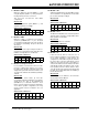
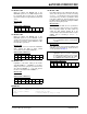
Affected Silicon Revisions
14. Module: UART
The UART error interrupt may not occur, or may
occur at an incorrect time, if multiple errors occur
during a short period of time.
Work around
Read the error flags in the UxSTA register
whenever a byte is received to verify the error
status. In most cases, these bits will be correct,
even if the UART error interrupt fails to occur.
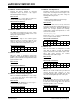
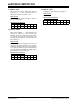
Affected Silicon Revisions
15. Module: UART
When the UART is operating in 8-bit mode
(PDSEL = 0x) and using the IrDA encoder/decoder
(IREN = 1), the module incorrectly transmits a data
payload of 80h as 00h.
Work around
None.
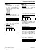
Affected Silicon Revisions
16. Module: Internal Voltage Regulator
When the VREGS bit (RCON<8>) is set to a logic
‘0’, the device may Reset and a higher sleep
current may be observed.
Work around
Ensure VREGS bit (RCON<8>) is set to a logic ‘1’
for device Sleep mode operation.
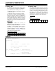
Affected Silicon Revisions
17. Module: PSV Operations
An address error trap occurs in certain addressing
modes when accessing the first four bytes of an
PSV page. This occurs only when using the
following addressing modes:
•MOV.D
• Register Indirect Addressing (word or byte
mode) with pre/post-decrement
Work around
Do not perform PSV accesses to any of the first
four bytes using the above addressing modes. For
applications using the C language, MPLAB C30
version 3.11 or higher, provides the following
command-line switch that implements a work
around for the erratum.
-merrata=psv_trap
Refer to the readme.txt file in the MPLAB C30
v3.11 tool suite for further details.
Affected Silicon Revisions
18. Module: I
2
C
When the I
2
C module is configured as a 10-bit
slave with an address of 0x02, the I2CxRCV
register content for the lower address byte is 0x01
rather than 0x02; however, the module
acknowledges both address bytes.
Work around
None.
Affected Silicon Revisions
19. Module: I
2
C
With the I
2
C module enabled, the port bits and
external interrupt input functions (if any)
associated with the SCL and SDA pins do not
reflect the actual digital logic levels on the pins.
Work around
If the SDA and/or SCL pins need to be polled,
these pins should be connected to other port pins
in order to be read correctly. This issue does not
affect the operation of the I
2
C module.
Affected Silicon Revisions
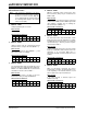
A2 A3 A4 A5
X
A2 A3 A4 A5
XXX
X
A2 A3 A4
A5
XXX
X
A2 A3 A4
A5
XXX
X
A2 A3 A4 A5
XXX
X
A2 A3 A4
A5
XXX
X
A2 A3 A4
A5
XXX
X