
Information

dsPIC33FJ12MC201/202
DS80461G-page 2 2010-2012 Microchip Technology Inc.
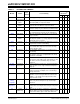
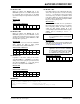
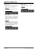
TABLE 2: SILICON ISSUE SUMMARY
Module Feature
Item
Number
Issue Summary
Affected
Revisions
(1)
A2 A3 A4 A5
JTAG Flash
Programming
1. JTAG programming does not work. X X X X
UART High-Speed
Mode
2. UART receptions may be corrupted if the Baud Rate
Generator (BRG) is set up for 4x mode.
XXXX
UART High-Speed
Mode
3. The auto-baud feature may not calculate the correct
baud rate when the BRG is set up for 4x mode.
XXXX
UART Auto-Baud 4. With the auto-baud feature selected, the Sync Break
character (0x55) may be loaded into the FIFO as data.
XXXX
UART Auto-Baud 5. The auto-baud feature measures baud rate inaccurately
for certain baud rate and clock speed combinations.
XXXX
UART Auto-Baud 6. When an auto-baud is detected, the receive interrupt
may occur twice.
XXXX
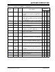
UART High-Speed
Mode
7. When the UART is in 4x mode (BRGH = 1) and using
two Stop bits (STSEL = 1), it may sample the first Stop
bit instead of the second one.
XXXX
UART IR Mode 8. The 16x baud clock signal on the BCLK pin is present
only when the module is transmitting.
XXXX
Interrupt
Controller
Idle Mode 9. If a clock failure occurs when the device is in Idle mode,
the oscillator failure trap does not vector to the Trap
Service Routine (TSR).
XXXX
SPI SCKx Pins 10. The SPIxCON1 DISSCK bit does not influence port
functionality.
XXXX
I
2
C™™SFR Writes11. The BCL bit in I2CSTAT can only be cleared with a 16-
bit operation, and can be corrupted with 1-bit or 8-bit
operations on I2CSTAT.
XXXX
I
2
C 10-bit
Addressing
12. When the I
2
C module is configured for 10-bit address-
ing using the same address bits (A10 and A9) as other
I
2
C devices, the A10 and A9 bits may not work as
expected.
XXXX
Product
Identification
Extended
Temperature
13. Revision A2 devices marked as extended temperature
range (E) devices only support industrial temperature
range (I).
X
UART Interrupts 14. The UART error interrupt may not occur, or may occur
at an incorrect time, if multiple errors occur during a
short period of time.
XXXX
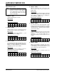
UART IR Mode 15. When the UART module is operating in 8-bit mode
(PDSEL = 0x) and using the IrDA
®
encoder/decoder
(IREN = 1), the module incorrectly transmits a data
payload of 80h as 00h.
XXXX
Internal
Voltage
Regulator
Sleep Mode 16. When the VREGS bit (RCON<8>) is set to a logic ‘0’,
device may Reset and higher sleep current may be
observed.
XXXX
PSV
Operations
— 17. An address error trap occurs in certain addressing
modes when accessing the first four bytes of any PSV
page.
XXXX
I
2
C 10-bit
Addressing
18. When the I
2
C module is configured as a 10-bit slave
with an address of 0x02, the I2CxRCV register content
for the lower address byte is 0x01 rather than 0x02.
XXXX
Note 1: Only those issues indicated in the last column apply to the current silicon revision.