
Information


© 2010 Microchip Technology Inc. DS70152H-page 63
dsPIC33F/PIC24H PROGRAMMING SPECIFICATION
APPENDIX C: DIAGNOSTIC AND
CALIBRATION
REGISTERS
For dsPIC33FJ06GS101/102/202, dsPIC33FJ16GS402/
404/502/504, dsPIC33FJ32GS406/606/608/610 and
dsPIC33FJ64GS406/606/608/610 devices, the last six
instruction words of program memory store diagnostic
and calibration information. Any development tool that
modifies this memory must take care to preserve the data
contained in these registers.
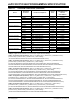
Table C-1 provides an example of how the diagnostic
and calibration registers are read. This table can be
added to the programming executive between steps 1
and 2.
Table C-2 shows an example of how the diagnostic and
calibration registers are restored once the program
memory has been erased. This table can be added to
the programming executive between steps 4 and 5.
TABLE C-1: READ DIAGNOSTIC AND CALIBRATION REGISTERS
Command (Binary) Data (Hex) Description
Step 1: Initialize pointer to RAM.
0000 208006 MOV #0x800, W6
0000 000000 NOP
Step 2: Fill section of RAM.
0000 EB9B00 SETM [W6++]
0000 000000 NOP
Step 3: Repeat step two: 0x67 times.
Step 4: Initialize pointers to read diagnostic and Calibration Words for storage.
0000 200800 MOV #0x80, W0
0000 880190 MOV W0, TBLPAG
0000 207F47 MOV #0x7F4, W7
0000 208AE6 MOV #0x8AE, W6
0000 000000 NOP
Step 5: Read in diagnostic and Calibration Words.
0000 BA1B17 TBLRDL[W7], [W6++]
0000 000000 NOP
0000 000000 NOP
0000 BADB37 TBLRDH.B[W7++], [W6++]
0000 000000 NOP
0000 000000 NOP
0000 BADB57 TBLRDH.B[++W7], [W6++]
0000 000000 NOP
0000 000000 NOP
0000 BA1B37 TBLRDL[W7++], [W6++]
0000 000000 NOP
0000 000000 NOP
Step 6: Repeat step 5 three times to read all 6 instruction words.