
Information


© 2010 Microchip Technology Inc. DS70152H-page 47
dsPIC33F/PIC24H PROGRAMMING SPECIFICATION
5.9 Reading Configuration Memory
The procedure for reading configuration memory is
similar to the procedure for reading code memory,
except that 16-bit data words are read (with the upper
byte read being all ‘0’s) instead of 24-bit words. Since
there are twelve Configuration registers, they are read
one register at a time.
Table 5-9 shows the ICSP programming details for
reading all of the configuration memory. Note that the
TBLPAG register is hard coded to 0xF8 (the upper byte
address of configuration memory) and the read pointer,
W6, is initialized to 0x0000.
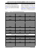
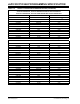
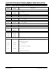
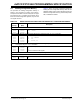
TABLE 5-9: SERIAL INSTRUCTION EXECUTION FOR READING ALL CONFIGURATION MEMORY
Command
(Binary)
Data
(Hex)
Description
Step 1: Exit the Reset vector.
0000
0000
0000
040200
040200
000000
GOTO 0x200
GOTO 0x200
NOP
Step 2: Initialize TBLPAG, the read pointer (W6) and the write pointer (W7) for TBLRD instruction.
0000
0000
0000
0000
0000
200F80
880190
EB0300
207847
000000
MOV #0xF8, W0
MOV W0, TBLPAG
CLR W6
MOV #VISI, W7
NOP
Step 3: Read the Configuration register and write it to the VISI register (located at 0x784) and clock out the
VISI register using the REGOUT command.
0000
0000
0000
0001
BA0BB6
000000
000000
<VISI>
TBLRDL [W6++], [W7]
NOP
NOP
Clock out contents of VISI register.
Step 4: Repeat step 3 twelve times to read all the Configuration registers.
Step 5: Reset device internal PC.
0000
0000
040200
000000
GOTO 0x200
NOP