
Information


dsPIC33F/PIC24H PROGRAMMING SPECIFICATION
DS70152H-page 24 © 2010 Microchip Technology Inc.
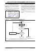
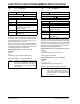
FIGURE 4-2: PROGRAMMING EXECUTIVE – PROGRAMMER COMMUNICATION PROTOCOL
4.2 Programming Executive
Commands
The programming executive command set is shown in
Table 4-1. This table contains the opcode, mnemonic,
length, time out and description for each command.
Functional details on each command are provided in
the command descriptions (Section 4.2.4 “Command
Descriptions”).
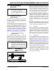
4.2.1 COMMAND FORMAT
All programming executive commands have a general
format consisting of a 16-bit header and any required
data for the command (see Figure 4-3). The 16-bit
header consists of a 4-bit opcode field, which is used to
identify the command, followed by a 12-bit command
length field.
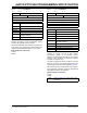
FIGURE 4-3: COMMAND FORMAT
The command opcode must match one of those in the
command set. Any command that is received which
does not match the list in Table 4-1 will return a “NACK”
response (see Section 4.3.1.1 “Opcode Field”).
The command length is represented in 16-bit words
since the SPI operates in 16-bit mode. The
programming executive uses the command length field
to determine the number of words to read from the SPI
port. If the value of this field is incorrect, the command
will not be properly received by the programming
executive.
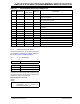
4.2.2 PACKED DATA FORMAT
When 24-bit instruction words are transferred across
the 16-bit SPI interface, they are packed to conserve
space using the format illustrated in Figure 4-4. This
format minimizes traffic over the SPI and provides the
programming executive with data that is properly
aligned for performing table write operations.
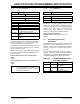
FIGURE 4-4: PACKED INSTRUCTION
WORD FORMAT
4.2.3 PROGRAMMING EXECUTIVE
ERROR HANDLING
The programming executive will “NACK” all
unsupported commands. Additionally, due to the
memory constraints of the programming executive, no
checking is performed on the data contained in the
programmer command. It is the responsibility of the
programmer to command the programming executive
with valid command arguments or the programming
operation may fail. Additional information on error
handling is provided in Section 4.3.1.3 “QE_Code
Field”.
1 2 15 16
1 2 15 16
PGCx
PGDx
PGCx = Input
PGCx = Input (Idle)
Host Transmits
Last Command Word
PGDx = Input
PGDx = Output
P8
1 2 15 16
MSB X X X LSB
MSB X X X LSB
MSB X X X LSB
1 0
P9b
PGCx = Input
PGDx = Output
P9a
Programming Executive
Processes Command
Host Clocks Out Response
Note 1: A delay of 25 ms is required between commands.
15 12 11 0
Opcode Length
Command Data First Word (if required)
•
•
Command Data Last Word (if required)
Note: When the number of instruction words
transferred is odd, MSB2 is zero and
LSW2 cannot be transmitted.
15 8 7 0
LSW1
MSB2 MSB1
LSW2
LSWx: Least Significant 16 bits of instruction word
MSBx: Most Significant Byte of instruction word