
Information


dsPIC33F/PIC24H PROGRAMMING SPECIFICATION
DS70152H-page 14 © 2010 Microchip Technology Inc.
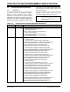
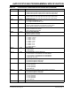
IESO FOSCSEL Two-Speed Oscillator Start-Up Enable bit
1 = Start-Up device with FRC, then automatically switch to the user-selected
oscillator source when ready
0 = Start-Up device with user-selected oscillator source
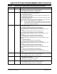
FNOSC<2:0> FOSCSEL Initial Oscillator Source Selection bits
111 = Internal Fast RC (FRC) oscillator with postscaler
110 = Internal Fast RC (FRC) oscillator with divide-by-16
101 = LPRC oscillator
100 = Secondary (LP) oscillator
011 = Primary (XT, HS, EC) oscillator with PLL
010 = Primary (XT, HS, EC) oscillator
001 = Internal Fast RC (FRC) oscillator with PLL
000 = FRC oscillator
FCKSM<1:0> FOSC Clock Switching Mode bits
1x = Clock switching is disabled, Fail-Safe Clock Monitor is disabled
01 = Clock switching is enabled, Fail-Safe Clock Monitor is disabled
00 = Clock switching is enabled, Fail-Safe Clock Monitor is enabled
IOL1WAY FOSC Peripheral Pin Select Configuration
1 = Allow only one reconfiguration
0 = Allow multiple reconfigurations
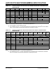
OSCIOFNC FOSC OSC2 Pin Function bit (except in XT and HS modes)
1 = OSC2 is clock output
0 = OSC2 is general purpose digital I/O pin
POSCMD<1:0> FOSC Primary Oscillator Mode Select bits
11 = Primary oscillator disabled
10 = HS crystal oscillator mode
01 = XT crystal oscillator mode
00 = EC (external clock) mode
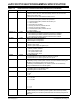
PLLKEN FWDT PLL Lock Enable bit
1 = Clock switch to PLL source waits for valid PLL lock signal
0 = Clock switch to PLL source ignores PLL lock signal
FWDTEN FWDT Watchdog Enable bit
1 = Watchdog always enabled (LPRC oscillator cannot be disabled. Clearing the
SWDTEN bit in the RCON register will have no effect)
0 = Watchdog enabled/disabled by user software (LPRC can be disabled by
clearing the SWDTEN bit in the RCON register)
WINDIS FWDT Watchdog Timer Window Enable bit
1 = Watchdog Timer in Non-Window mode
0 = Watchdog Timer in Window mode
WDTPRE FWDT Watchdog Timer Prescaler bit
1 = 1:128
0 = 1:32
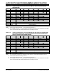
WDTPOST FWDT Watchdog Timer Postscaler bits
1111 = 1:32,768
1110 = 1:16,384
•
•
•
0001 = 1:2
0000 = 1:1
PWMPIN FPOR Motor Control PWM Module Pin mode
1
= PWM module pins controlled by PORT register at device Reset (tri-stated)
0 = PWM module pins controlled by PWM module at device Reset (configured as
output pins)
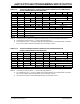
TABLE 3-2: dsPIC33F/PIC24H CONFIGURATION BITS DESCRIPTION (CONTINUED)
Bit Field Register Description