
Information

2009-2013 Microchip Technology Inc. DS80442J-page 3
dsPIC33FJ32MC302/304, dsPIC33FJ64MCX02/X04 and dsPIC33FJ128MCX02/X04
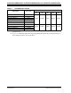
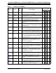
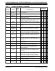
TABLE 2: SILICON ISSUE SUMMARY
Module Feature
Item
Number
Issue Summary
Affected
Revisions
(1)
A1 A2 A3 A4 A5
UART IR Mode 1. The 16x baud clock signal on the BCLK pin is present
only when the module is transmitting.
XXXXX
UART High-Speed
Mode
2. When the UART is in 4x mode (BRGH = 1) and using
two Stop bits (STSEL = 1), it may sample the first Stop
bit instead of the second one.
XXXXX
SPI Transmit
Operation
3. The SPIx Transmit Buffer Full (SPITBF) flag does not
get set immediately after writing to the buffer.
XXXXX
SPI Frame Mode 4. The SPIx module will generate incorrect frame
synchronization pulses in Frame Master mode if
FRMDLY = 1.
XXXXX
I
2
C™™SFR Writes5. The BCL bit in I2CxSTAT can only be cleared with word
instructions, and can be corrupted with byte instructions
and bit operations.
XXXXX
I
2
C 10-Bit
Addressing
6. When the I
2
C module is configured for 10-bit addressing,
using the same Address bits (A10 and A9) as other I
2
C
devices, A10 and A9 bits may not work as expected.
XXXXX
I
2
C 10-Bit
Addressing
7. When the I
2
C module is configured as a 10-bit slave
with an address of 0x02, the I2CxRCV register content
for the lower address byte is 0x01 rather than 0x02.
XXXXX
I
2
C — 8. With the I
2
C module enabled, the PORT bits and
external interrupt input functions (if any) associated with
SCLx and SDAx pins will not reflect the actual digital
logic levels on the pins.
XXXXX
I
2
C 10-Bit
Addressing
9. The 10-bit slave does not set the RBF flag or load the
I2CxRCV register, on address match if the Least
Significant bits (LSbs) of the address are the same as
the 7-bit reserved addresses.
XXXXX
I
2
C — 10. After the ACKSTAT bit is set when receiving a NACK, it
may be cleared by the reception of a Start or Stop bit.
XXXXX
UART Interrupts 11. The UART error interrupt may not occur, or may occur
at an incorrect time, if multiple errors occur during a
short period of time.
XXXXX
UART IR Mode 12. When the UART module is operating in 8-bit mode
(PDSEL<1:0> = 0x) and using the IrDA
®
encoder/
decoder (IREN = 1), the module incorrectly transmits a
data payload of 80h as 00h.
XXXXX
Comparator Output Pin 13. When the CxOUTEN (CMCON) bit is set, the
comparator output pin cannot be used as a general
purpose I/O pin, even if the comparator is disabled.
XXXXX
Internal
Voltage
Regulator
Sleep Mode 14. When the VREGS bit (RCON<8>) is set to a logic ‘0’, the
device may reset and higher Sleep current may be
observed.
XXXXX
PSV
Operations
— 15. An address error trap occurs in certain addressing modes
when accessing the first four bytes of any PSV page.
XXXXX
ECAN™ Sleep Mode 16. The WAKIF bit in the CiINTF register cannot be cleared
by software instruction after the device is interrupted
from Sleep due to activity on the CAN bus.
XXXXX
Note 1: Only those issues indicated in the last column apply to the current silicon revision.