
Datasheet


© 2007-2012 Microchip Technology Inc. DS70291G-page 233
dsPIC33FJ32MC302/304, dsPIC33FJ64MCX02/X04 AND dsPIC33FJ128MCX02/X04
18.0 SERIAL PERIPHERAL
INTERFACE (SPI)
The Serial Peripheral Interface (SPI) module is a
synchronous serial interface useful for communicating
with other peripheral or microcontroller devices. These
peripheral devices can be serial EEPROMs, shift
registers, display drivers, analog-to-digital converters,
etc. The SPI module is compatible with Motorola
®
SPI
and SIOP.
Each SPI module consists of a 16-bit shift register,
SPIxSR (where x = 1 or 2), used for shifting data in and
out, and a buffer register, SPIxBUF. A control register,
SPIxCON, configures the module. Additionally, a status
register, SPIxSTAT, indicates status conditions.
The serial interface consists of 4 pins:
• SDIx (serial data input)
• SDOx (serial data output)
• SCKx (shift clock input or output)
• SSx
(active-low slave select)
In Master mode operation, SCK is a clock output. In
Slave mode, it is a clock input.
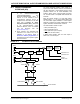
FIGURE 18-1: SPI MODULE BLOCK DIAGRAM
Note 1: This data sheet summarizes the features
of the dsPIC33FJ32MC302/304,
dsPIC33FJ64MCX02/X04 and
dsPIC33FJ128MCX02/X04 family of
devices. It is not intended to be a
comprehensive reference source. To
complement the information in this data
sheet, refer to Section 18. “Serial
Peripheral Interface (SPI)” (DS70206)
of the “dsPIC33F/PIC24H Family
Reference Manual”, which is available
from the Microchip web site
(www.microchip.com).
2: Some registers and associated bits
described in this section may not be
available on all devices. Refer to
Section 4.0 “Memory Organization” in
this data sheet for device-specific register
and bit information.
Internal Data Bus
SDIx
SDOx
SSx
SCKx
SPIxSR
bit 0
Shift Control
Edge
Select
F
CY
Primary
1:1/4/16/64
Enable
Prescaler
Sync
SPIxBUF
Control
Transfer
Transfer
Write SPIxBUF
Read SPIxBUF
16
SPIxCON1<1:0>
SPIxCON1<4:2>
Master Clock
Clock
Control
Secondary
Prescaler
1:1 to 1:8
SPIxRXB SPIxTXB