
Datasheet


dsPIC33FJ32GP302/304, dsPIC33FJ64GPX02/X04, AND dsPIC33FJ128GPX02/X04
DS70292G-page 342 © 2007-2012 Microchip Technology Inc.
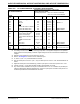
TABLE 30-7: DC CHARACTERISTICS: POWER-DOWN CURRENT (IPD)
DC CHARACTERISTICS
Standard Operating Conditions: 3.0V to 3.6V
(unless otherwise stated)
Operating temperature -40°C ≤ TA ≤ +85°C for Industrial
-40°C ≤T
A ≤+125°C for Extended
Parameter
No.
(3)
Typical
(2)
Max Units Conditions
Power-Down Current (IPD)
(1)
DC60d 24 68 μA -40°C
3.3V Base Power-Down Current
(3,4)
DC60a 28 87 μA+25°C
DC60b 124 292 μA+85°C
DC60c 350 1000 μA +125°C
DC61d 8 13 μA -40°C
3.3V Watchdog Timer Current: ΔI
WDT
(3,5)
DC61a 10 15 μA+25°C
DC61b 12 20 μA+85°C
DC61c 13 25 μA +125°C
Note 1: I
PD (Sleep) current is measured as follows:
• CPU core is off (i.e., Sleep mode), oscillator is configured in EC mode and external clock active,
OSC1 is driven with external square wave from rail-to-rail (EC clock overshoot/undershoot < 250 mV
required)
• CLKO is configured as an I/O input pin in the Configuration word
• All I/O pins are configured as inputs and pulled to V
SS
•MCLR = VDD, WDT and FSCM are disabled, all peripheral modules are disabled (PMDx bits are all
‘1’s)
• RTCC is disabled
• JTAG is disabled
2: Data in the “Typ” column is at 3.3V, +25ºC unless otherwise stated.
3: The Watchdog Timer Current is the additional current consumed when the WDT module is enabled. This
current should be added to the base I
PD current.
4: These currents are measured on the device containing the most memory in this family.
5: These parameters are characterized, but are not tested in manufacturing.