
Datasheet


dsPIC33FJ32GP302/304, dsPIC33FJ64GPX02/X04, AND dsPIC33FJ128GPX02/X04
DS70292G-page 218 © 2007-2012 Microchip Technology Inc.
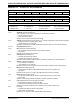
REGISTER 17-2: I2CxSTAT: I2Cx STATUS REGISTER
R-0 HSC R-0 HSC U-0 U-0 U-0 R/C-0 HS R-0 HSC R-0 HSC
ACKSTAT TRSTAT
— — — BCL GCSTAT ADD10
bit 15 bit 8
R/C-0 HS R/C-0 HS R-0 HSC R/C-0 HSC R/C-0 HSC R-0 HSC R-0 HSC R-0 HSC
IWCOL I2COV D_A P S R_W RBF TBF
bit 7 bit 0
Legend: U = Unimplemented bit, read as ‘0’ C = Clear only bit
R = Readable bit W = Writable bit HS = Set in hardware HSC = Hardware set/cleared
-n = Value at POR ‘1’ = Bit is set ‘0’ = Bit is cleared x = Bit is unknown
bit 15 ACKSTAT: Acknowledge Status bit
(when operating as I
2
C™ master, applicable to master transmit operation)
1 = NACK received from slave
0 = ACK received from slave
Hardware set or clear at end of slave Acknowledge.
bit 14 TRSTAT: Transmit Status bit (when operating as I
2
C master, applicable to master transmit operation)
1 = Master transmit is in progress (8 bits + ACK)
0 = Master transmit is not in progress
Hardware set at beginning of master transmission. Hardware clear at end of slave Acknowledge.
bit 13-11 Unimplemented: Read as ‘0’
bit 10 BCL: Master Bus Collision Detect bit
1 = A bus collision has been detected during a master operation
0 = No collision
Hardware set at detection of bus collision.
bit 9 GCSTAT: General Call Status bit
1 = General call address was received
0 = General call address was not received
Hardware set when address matches general call address. Hardware clear at Stop detection.
bit 8 ADD10: 10-bit Address Status bit
1 = 10-bit address was matched
0 = 10-bit address was not matched
Hardware set at match of 2nd byte of matched 10-bit address. Hardware clear at Stop detection.
bit 7 IWCOL: Write Collision Detect bit
1 = An attempt to write the I2CxTRN register failed because the I
2
C module is busy
0 = No collision
Hardware set at occurrence of write to I2CxTRN while busy (cleared by software).
bit 6 I2COV: Receive Overflow Flag bit
1 = A byte was received while the I2CxRCV register is still holding the previous byte
0 = No overflow
Hardware set at attempt to transfer I2CxRSR to I2CxRCV (cleared by software).
bit 5 D_A: Data/Address bit (when operating as I
2
C slave)
1 = Indicates that the last byte received was data
0 = Indicates that the last byte received was device address
Hardware clear at device address match. Hardware set by reception of slave byte.
bit 4 P: Stop bit
1 = Indicates that a Stop bit has been detected last
0 = Stop bit was not detected last
Hardware set or clear when Start, Repeated Start or Stop detected.