
Information

dsPIC33FJ32GP302/304, dsPIC33FJ64GPX02/X04 and dsPIC33FJ128GPX02/X04
DS80000443K-page 8 2009-2013 Microchip Technology Inc.
17. Module: ECAN
The ECAN module may not store received data in
the correct location. When this occurs, the receive
buffers will become corrupted. In addition, it is also
possible for the transmit buffers to become
corrupted. This issue is more likely to occur as the
CAN bus speed approaches 1 Mbps.
Work around
Do not use the DMA with ECAN in Peripheral
Indirect mode. Use the DMA in Register Indirect
mode, Continuous mode enabled and Ping Pong
mode disabled. The receive DMA channel count
should be set to 8 words. The transmit DMA
channel count should be set for the actual
message size (maximum of 7 words for Extended
CAN messages and 6 words for Standard CAN
messages). To simplify application error handling
while using this mode, only one TX buffer should
be used. While message filtering is not affected,
messages will not be stored at distinct RX buffers.
Instead, all messages are stored contiguously in
memory. The start of this memory is pointed to by
the receive DMA channel. The application must
still clear the RXFULx flags and other interrupt
flags. The application must manage the RX buffer
memory.
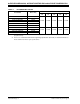
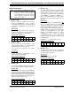
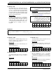
Affected Silicon Revisions
18. Module: CPU
The EXCH instruction does not execute correctly.
Work around
If writing source code in assembly, the
recommended work around is to replace:
EXCH Wsource, Wdestination
with:
PUSH Wdestination
MOV Wsource, Wdestination
POP Wsource
If using the MPLAB C30 C compiler, specify the
compiler option: -merrata=exch (Project > Build
Options > Projects > MPLAB C30 > Use Alternate
Settings).
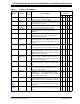
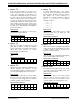
Affected Silicon Revisions
19. Module: SPI
Writing to the SPIxBUF register as soon as the
TBF bit is cleared will cause the SPIx module to
ignore the written data. Applications which use
SPIx with DMA will not be affected by this erratum.
Work around
After the TBF bit is cleared, wait for a minimum
duration of one SPI clock before writing to the
SPIxBUF register.
Alternatively, do one of the following:
• Poll the RBF bit and wait for it to get set before
writing to the SPIxBUF register
• Poll the SPI interrupt flag and wait for it to get
set before writing to the SPIxBUF register
• Use an SPI Interrupt Service Routine
•Use DMA
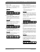
Affected Silicon Revisions
20. Module: UART
The UARTx module will not generate consecutive
Break characters. Trying to perform a back-to-
back Break character transmission will cause the
UARTx module to transmit the dummy character
used to generate the first Break character instead
of transmitting the second Break character. Break
characters are generated correctly if they are
followed by non-Break character transmission.
Work around
None.
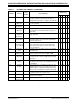
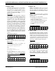
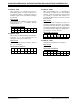
Affected Silicon Revisions
21. Module: Audio DAC
The audio DAC positive differential output voltage
and negative differential output voltage
(Parameters DA01 and DA02, respectively) may
not meet the specifications listed in the data sheet.
Work around
None.
Affected Silicon Revisions
A1 A2 A3 A4 A5
XXX
A1 A2 A3 A4 A5
XXXX
X
A1 A2 A3 A4 A5
XXXX
X
A1 A2 A3 A4
A5
XXXX
X
A1 A2 A3 A4
A5
XXX