
Specifications

© 2006 Microchip Technology Inc. DS70183A-page 16-7
Section 16. Analog-to-Digital Converter (ADC)
A
D
C
16
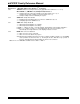
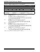
Register 16-2: ADxCON2: ADCx Control Register 2
(1)
R/W-0 R/W-0 R/W-0 U-0 U-0 R/W-0 R/W-0 R/W-0
VCFG<2:0> — — CSCNA CHPS<1:0>
bit 15 bit 8
R-0 U-0 R/W-0 R/W-0 R/W-0 R/W-0 R/W-0 R/W-0
BUFS — SMPI<3:0> BUFM ALTS
bit 7 bit 0
Legend:
R = Readable bit W = Writable bit U = Unimplemented bit, read as ‘0’
-n = Value at POR ‘1’ = Bit is set ‘0’ = Bit is cleared x = Bit is unknown
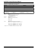
bit 15-13 VCFG<2:0>: Converter Voltage Reference Configuration bits
bit 12-11 Unimplemented: Read as ‘0’
bit 10 CSCNA: Input Scan Select bit
1 = Scan inputs for CH0+ during Sample A bit
0 = Do not scan inputs
bit 9-8 CHPS<1:0>: Channel Select bits
When AD12B = 1, CHPS<1:0> is: U-0, Unimplemented, Read as ‘0’
1x = Converts CH0, CH1, CH2 and CH3
01 = Converts CH0 and CH1
00 = Converts CH0
bit 7 BUFS: Buffer Fill Status bit (only valid when BUFM = 1)
1 = ADC is currently filling the second half of the buffer. The user application should access data in
the first half of the buffer
0 = ADC is currently filling the first half of the buffer. The user application should access data in the
second half of the buffer.
bit 6 Unimplemented: Read as ‘0’
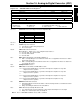
bit 5-2 SMPI<3:0>: Increment Rate for DMA Addresses bits
1111 = Increments the DMA address or generates interrupt after completion of every 16th
sample/conversion operation
1110 = Increments the DMA address or generates interrupt after completion of every 15th
sample/conversion operation
• • •
0001 = Increments the DMA address or generates interrupt after completion of every 2nd
sample/conversion operation
0000 = Increments the DMA address or generates interrupt after completion of every
sample/conversion operation
bit 1 BUFM: Buffer Fill Mode Select bit
1 = Starts buffer filling the first half of the buffer on the first interrupt and the second half of the buffer
on next interrupt
0 = Always starts filling the buffer from the start address.
bit 0 ALTS: Alternate Input Sample Mode Select bit
1 = Uses channel input selects for Sample A on first sample and Sample B on next sample
0 = Always uses channel input selects for Sample A
Note 1: The ‘x’ in ADxCON2 and ADCx refers to ADC 1 or ADC 2.
VREFH VREFL
000 AVDD Avss
001 External VREF+Avss
010 A
VDD External VREF-
011 External VREF+ External VREF-
1xx AVDD Avss