
Specifications


© 2006 Microchip Technology Inc. DS70183A-page 16-59
Section 16. Analog-to-Digital Converter (ADC)
A
D
C
16
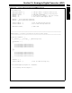
Example 16-5: Code for Alternate Sampling Using DMA (Continued)
AD1CON3bits.ADRC = 0; // ADC Clock is derived from Systems Clock
AD1CON3bits.ADCS = 63;
// ADC Conversion Clock Tad=Tcy*(ADCS+1)=(1/40M)*64 = 1.6us(625Khz)
// ADC Conversion Time for 10-bit Tc=12*Tab = 19.2us
AD1CON1bits.ADDMABM = 0; // DMA buffers are built in scatter/gather mode
AD1CON2bits.SMPI = 1; // SMPI Must be programmed to 1 for this case
AD1CON4bits.DMABL = 4; // Each buffer contains 16 words
//AD1CHS0: A/D Input Select Register
AD1CHS0bits.CH0SA=4; // MUXA +ve input selection (AIN4) for CH0
AD1CHS0bits.CH0NA=0; // MUXA -ve input selection (Vref-) for CH0
AD1CHS0bits.CH0SB=5; // MUXB +ve input selection (AIN5) for CH0
AD1CHS0bits.CH0NB=0; // MUXB -ve input selection (Vref-) for CH0
//AD1PCFGH/AD1PCFGL: Port Configuration Register
AD1PCFGL=0xFFFF;
AD1PCFGH=0xFFFF;
AD1PCFGLbits.PCFG4 = 0; // AN4 as Analog Input
AD1PCFGLbits.PCFG5 = 0; // AN5 as Analog Input
IFS0bits.AD1IF = 0; // Clear the A/D interrupt flag bit
IEC0bits.AD1IE = 0; // Do Not Enable A/D interrupt
AD1CON1bits.ADON = 1; // Turn on the A/D converter
tglPinInit();
}
/*========================================================================================
Timer 3 is set up to time-out every 125 microseconds (8Khz Rate). As a result, the module
will stop sampling and trigger a conversion on every Timer3 time-out, i.e., Ts=125us.
==========================================================================================*/
void initTmr3()
{
TMR3 = 0x0000;
PR3 = 4999;
IFS0bits.T3IF = 0;
IEC0bits.T3IE = 0;
//Start Timer 3
T3CONbits.TON = 1;
}
// DMA0 configuration
// Direction: Read from peripheral address 0-x300 (ADC1BUF0) and write to DMA RAM
// AMODE: Peripheral Indirect Addressing Mode
// MODE: Continuous, Ping-Pong Mode
// IRQ: ADC Interrupt
// ADC stores results stored alternatively between DMA_BASE[0]/DMA_BASE[16] on every 16th DMA request
void initDma0(void)
{
DMA0CONbits.AMODE = 2; // Configure DMA for Peripheral indirect mode
DMA0CONbits.MODE = 2; // Configure DMA for Continuous Ping-Pong mode
DMA0PAD=(int)&ADC1BUF0;
DMA0CNT = (SAMP_BUFF_SIZE*2)-1;