
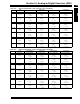
Specifications


© 2006 Microchip Technology Inc. DS70183A-page 16-53
Section 16. Analog-to-Digital Converter (ADC)
A
D
C
16
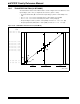
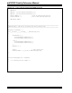
16.18 TRANSFER FUNCTION (12-BIT MODE)
The ideal transfer function of the ADC is shown in Figure 16-27. The difference of the input volt-
ages (V
INH – VINL) is compared to the reference (VREFH – VREFL).
• The first code transition (A) occurs when the input voltage is (V
REFH – VREFL/8192) or 0.5
LSb.
•The 00 0000 0001 code is centered at (V
REFH – VREFL/4096) or 1.0 LSb (B).
•The 10 0000 0000 code is centered at (2048*(V
REFH – VREFL)/4096) (C).
• An input voltage less than (1*(VREFH – VREFL)/8192) converts as 00 0000 0000 (D).
• An input greater than (8192*(VREFH – VREFL)/8192) converts as 11 1111 1111 (E).
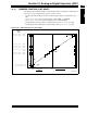
Figure 16-28: A/D Transfer Function (12-bit Mode)
1000 0000 0001 (= 2049)
1000 0000 0010 (= 2050)
1000 0000 0011 (= 2051)
0111 1111 1101 (= 2045)
0111 1111 1110 (= 2046)
0111 1111 1111 (= 2047)
1111 1111 1110 (= 4094)
1111 1111 1111 (= 4095)
0000 0000 0000 (= 0)
0000 0000 0001 (= 1)
Output
Code
1000 0000 0000 (= 2048)
(V
INH
– V
INL
)
V
REFL
V
REFH
– V
REFL
4096
2048*(V
REFH
– V
REFL
)
4096
V
REFH
V
REFL
+
V
REFL
+
(A)
(B)
(C)
(D)
(E)