
Specifications


© 2006 Microchip Technology Inc. DS70183A-page 16-45
Section 16. Analog-to-Digital Converter (ADC)
A
D
C
16
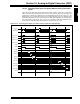
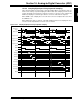
16.14.5 Sampling Eight Inputs Using Simultaneous Sampling
This and the next example demonstrate identical setups with the exception that this example
uses simultaneous sampling (SIMSAM = 1), and the following example uses sequential sam-
pling (SIMSAM = 0). Both examples use alternating inputs and specify differential inputs to the
Sample/Hold.
Figure 16-21 and Table 16-6 demonstrate simultaneous sampling. When converting more than
one channel and selecting simultaneous sampling, the ADC module samples all channels, then
performs the required conversions in sequence. In this example, with ASAM set, sampling begins
after the conversions complete.
Figure 16-21: Sampling Eight Inputs Using Simultaneous Sampling
ADC Clock
SAMP
DONE
Input to CH0
AN13-AN1
TSAMP
AD1IF
AN0
AN1
AN2
Input to CH1
Input to CH2
Input to CH3
Buffer[13]
Buffer[14]
Buffer[15]
AN14
TSAMP
AN3-AN6
AN4-AN7
AN5-AN8
AN14
TSAMP
AN3-AN6
AN4-AN7
AN5-AN8
ASAM
AN13-AN1
AN0
AN1
AN2
Buffer[0]
Buffer[1]
Buffer[2]
Buffer[3]
Buffer[12]
Conversion
Trigger
T
CONVTCONVTCONVTCONV TCONVTCONVTCONVTCONV TCONVTCONVTCONVTCONV