
Specifications


© 2006 Microchip Technology Inc. DS70183A-page 16-41
Section 16. Analog-to-Digital Converter (ADC)
A
D
C
16
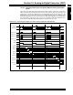
16.14.3 Sampling Three Inputs Frequently While Scanning Four Other
Inputs
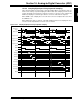
Figure 16-19 and Table 16-4 show how the ADC module could be configured to sample three
inputs frequently using Sample/Hold channels CH1, CH2 and CH3; while four other inputs are
sampled less frequently by scanning them using Sample/Hold channel CH0. In this case, only
MUX A inputs are used, and all four channels are sampled simultaneously. Four different inputs
(AN4, AN5, AN6, AN7) are scanned in CH0, whereas AN0, AN1 and AN2 are the fixed inputs for
CH1, CH2 and CH3, respectively. Thus, in every set of 16 samples, AN0, AN1 and AN2 are sam-
pled four times, while AN4, AN5, AN6 and AN7 are sampled only once each.
Figure 16-19: Converting Three Inputs, Four Times and Four Inputs, One Time/Interrupt
ADC Clock
SAMP
DONE
Input to CH0
AN4
TSAMP
AD1IF
TCONVTCONVTCONVTCONV
AN0
AN1
AN2
Input to CH1
Input to CH2
Input to CH3
Buffer[13]
Buffer[14]
Buffer[15]
AN5
TSAMP
AN0
AN1
AN2
AN7
TSAMP
AN0
AN1
AN2
ASAM
AN4
AN0
AN1
AN2
Buffer[0]
Buffer[1]
Buffer[2]
Buffer[3]
Buffer[12]
AN6
AN0
AN1
AN2
Conversion
Trigger
T
CONVTCONVTCONVTCONV TCONVTCONVTCONVTCONV