
Specifications


dsPIC33F Family Reference Manual
DS70183A-page 16-36 © 2006 Microchip Technology Inc.
16.13.2 USING DMA IN THE CONVERSION ORDER MODE
When the AADMABM bit (ADCON1<12>) = 1, the Conversion Order mode is enabled. In this
mode, the DMA channel can be configured for Register Indirect or Peripheral Indirect Address-
ing. All conversion results are stored in the user-specified DMA buffer area in the same order in
which the conversions are performed by the ADC module. In this mode, the buffer is not divided
into blocks allocated to different analog inputs. Rather the conversion results from different inputs
are interleaved according to the specific buffer fill modes being used.
In this configuration, the buffer pointer is always incremented by one word. In this case, the
SMPI<3:0> bits (ADxCON2<5:2>) must be cleared and the DMABL<2:0> bits (ADxCON4<2:0>)
are ignored.
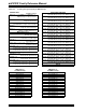
Figure 16-16 illustrates an example identical to the configuration in Figure 16-15, but using the
Conversion Order mode. In this example, the DMAxCNT register has been configured to gener-
ate the DMA interrupt after 16 conversion results have been obtained.
Figure 16-16: DMA Buffer in Conversion Order Mode
AN4 – SAMPLE 1
DMAxSTA
AN0 – SAMPLE 1
AN1 – SAMPLE 1
AN2 – SAMPLE 1
AN5 – SAMPLE 2
AN0 – SAMPLE 2
AN1 – SAMPLE 2
AN2 – SAMPLE 2
AN6 – SAMPLE 3
AN0 – SAMPLE 3
AN1 – SAMPLE 3
AN2 – SAMPLE 3
AN7 – SAMPLE 4
AN0 – SAMPLE 4
AN1 – SAMPLE 4
AN2 – SAMPLE 4