
Specifications


© 2006 Microchip Technology Inc. DS70183A-page 16-25
Section 16. Analog-to-Digital Converter (ADC)
A
D
C
16
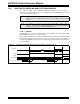
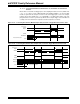
Example 16-3: Converting One Channel, Manual Sample Start,
T
AD Based Conversion Start Code
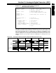
16.11.2.1 FREE RUNNING SAMPLE CONVERSION SEQUENCE
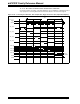
As shown in Figure 16-8, using the Auto-Convert Conversion Trigger mode (SSRC = 111) in
combination with the Auto-Sample Start mode (ASAM = 1), allows the ADC module to schedule
sample/conversion sequences with no intervention by the user or other device resources. This
“Clocked” mode allows continuous data collection after module initialization.
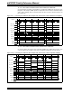
Figure 16-8: Converting One Channel, Auto-Sample Start, T
AD Based Conversion Start
Note: This A/D configuration must be enabled for the conversion rate of 750 ksps.
AD1PCFGL = 0xEFFF; // all PORTB = Digital; RB12 = analog
AD1CON1 = 0x00E0; // SSRC bit = 111 implies internal
// counter ends sampling and starts
// converting.
AD1CHS0= 0x000C; // Connect RB12/AN12 as CH0 input ..
// in this example RB12/AN12 is the input
AD1CSSL = 0;
AD1CON3 = 0x1F02; // Sample time = 31Tad, Tad = internal 2 Tcy
AD1CON2 = 0;
AD1CON1bits.ADON = 1; // turn ADC ON
while (1) // repeat continuously
{
AD1CON1bits.SAMP = 1; // start sampling then ...
// after 31Tad go to conversion
while (!AD1CON1bits.DONE);// conversion done?
ADCValue = ADC1BUF0; // yes then get ADC value
} // repeat
ADC Clock
SAMP
Buffer[1]
TSAMP
TCONV
DONE
= 16 TAD
TSAMP
TCONV
= 16 TAD
Buffer[0]
BSET AD1CON1,ASAM
Instruction Execution