
Specifications


dsPIC33F Family Reference Manual
DS70183A-page 16-24 © 2006 Microchip Technology Inc.
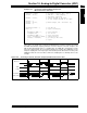
Example 16-2: Converting 1 Channel, Automatic Sample Start,
Manual Conversion Start Code
16.11.2 Clocked Conversion Trigger
When SSRC<2:0> =
111
, the conversion trigger is under A/D clock control. The Auto Sample Time
(SAMC<4:0>) bits (AD1CON3<12:8>) select the number of T
AD
clock cycles between the start of sam-
pling and the start of conversion. This trigger option provides the fastest conversion rates on multiple
channels. After the start of sampling, the ADC module counts a number of T
AD
clocks specified by the
SAMC bits.
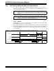
Equation 16-2: Clocked Conversion Trigger Time
When using only one Sample/Hold channel or simultaneous sampling, SAMC must always be pro-
grammed for at least one clock cycle. When using multiple Sample/Hold channels with sequential
sampling, programming SAMC for zero clock cycles results in the fastest possible conversion rate.
See Example 16-3 for code example.
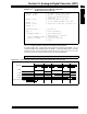
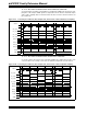
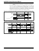
Figure 16-7: Converting 1 Channel, Manual Sample Start, TAD Based Conversion Start
AD1PCFGL = 0xFF7F; // all PORTB = Digital but RB7 = analog
AD1CON1 = 0x0004; // ASAM bit = 1 implies sampling ..
// starts immediately after last
// conversion is done
AD1CHS0= 0x0007; // Connect RB7/AN7 as CH0 input ..
// in this example RB7/AN7 is the input
AD1CSSL = 0;
AD1CON3 = 0x0002; // Sample time manual, Tad = internal 2 Tcy
AD1CON2 = 0;
AD1CON1bits.ADON = 1; // turn ADC ON
while (1) // repeat continuously
{
DelayNmSec(100); // sample for 100 mS
AD1CON1bits.SAMP = 0; // start Converting
while (!AD1CON1bits.DONE);// conversion done?
ADCValue = ADC1BUF0; // yes then get ADC value
} // repeat
TSMP = SAMC<4:0>*TAD
ADC Clock
SAMP
ADC1BUF0
TSAMP
TCONV
BSET AD1CON1,SAMP
Instruction Execution
DONE
= 16 TAD