
Specifications


© 2006 Microchip Technology Inc. DS70183A-page 16-15
Section 16. Analog-to-Digital Converter (ADC)
A
D
C
16
The number of Sample/Hold amplifiers, or channels per sample, used in the sample/convert
sequence is determined by the Channel Select (CHPS<1:0>) control bits in ADCx Control Reg-
ister 2 (ADxCON2<9:8>).
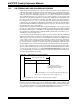
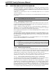
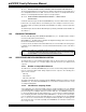
A sample/convert sequence that uses multiple Sample/Hold channels can be simultaneously
sampled or sequentially sampled, as controlled by the Simultaneous Sample Select (SIMSAM)
bit (ADxCON1<3>). Simultaneously sampling multiple signals ensures that the snapshot of the
analog inputs occurs at precisely the same time for all inputs. Sequential sampling takes a snap-
shot of each analog input just before conversion starts on that input. The sampling of multiple
inputs is not correlated.
Figure 16-3: Simultaneous and Sequential Sampling
The start time for sampling can be controlled in software by setting the ADC Sample Enable
(SAMP) control bit (ADxCON1<1>). The start of the sampling time can also be controlled auto-
matically by the hardware. When the ADC module operates in the Auto-Sample mode, the Sam-
ple/Hold amplifier(s) is reconnected to the analog input pin at the end of the conversion in the
sample/convert sequence. The auto-sample function is controlled by the ADC Sample Auto-Start
(ASAM) control bit (ADxCON1<2>).
The conversion trigger source ends the sampling time and begins an A/D conversion or a
sample/convert sequence. The conversion trigger source is selected by the Sample Clock
Source Select (SSRC<2:0>) control bits (ADxCON1<7:5>. The conversion trigger can be taken
from a variety of hardware sources, or can be controlled manually in software by clearing the
SAMP control bit. One of the conversion trigger sources is an auto-conversion. The time between
auto-conversions is set by a counter and the ADC clock. The Auto-Sample mode and auto-con-
version trigger can be used together to provide endless automatic conversions without software
intervention.
An interrupt can be generated at the end of each sample/convert sequence or after multiple
sample/convert sequences, as determined by the value of the Samples Per Interrupt
(SMPI<3:0>) control bits (ADxCON2<5:2>). The number of sample/convert sequences between
interrupts can vary between 1 and 16. The total number of conversion results between interrupts
is the product of the channels per sample and the SMPI<3:0> value. However, since only one
conversion result is stored in ADCxBUF0, each execution of the interrupt service routine can be
used to read only one conversion result.
If multiple conversion results need to be buffered, a DMA buffer should be used to store the con-
version results. In this case, the SMPI<3:0> bits are used to select how often the DMA RAM
buffer pointer is incremented. The frequency of incrementing the DMA RAM buffer pointer should
not exceed the DMA RAM buffer length.
Note: The 12-bit ADC configuration can only perform one conversion in a single sam-
ple/convert sequence. The CHPS bits are irrelevant in this case.
AN0
AN1
AN2
AN3
Simultaneous
Sampling
Sequential
Sampling