
Specifications


dsPIC33F/PIC24H Family Reference Manual
DS70323E-page 43-98 © 2008-2012 Microchip Technology Inc.
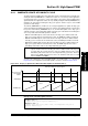
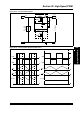
43.16.4 Variable Phase PWM
The Variable Phase PWM, illustrated in Figure 43-51, constantly changes the phase shift among
PWM channels to control the flow of power, which is in contrast with most PWM circuits that vary
the duty cycle of PWM signal to control power flow. In variable phase applications, the PWM duty
cycle is often maintained at 50 percent. The phase shift value is available to all PWM modes that
use the master time base.
The variable phase PWM is used in newer power conversion topologies that are designed to
reduce switching losses. In the standard PWM methods, when a transistor switches between the
conducting state and non-conducting state (and vice versa), the transistor is exposed to the full
current and voltage condition during the time when the transistor turns ON or OFF and the power
loss (V * I * T
SW * FPWM) becomes appreciable at high frequencies.
The Zero Voltage Switching (ZVS) and Zero Current Switching (ZVC) circuit topologies attempt
to use quasi-resonant techniques that shift either the voltage or the current waveforms relative
to each other to change the value of voltage or the current to zero when the transistor turns ON
or OFF. If either the current or the voltage is zero, no switching loss occurs.
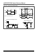
Figure 43-51: Variable Phase PWM
PWM1H
PWM1L
PWM2H
PWM2L
Variable Phase Shift
Duty Cycle
PWM1H
Period
Duty Cycle
Duty Cycle
Phase 2 (old value)
Duty Cycle
PWM2H
Phase 2 (new value)
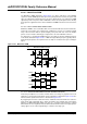
Full-Bridge ZVT Converter
T1
+V
IN
PWM1H
PWM1L
PWM2L
PWM2H
+
V
OUT