
Specifications


dsPIC33F/PIC24H Family Reference Manual
DS70323E-page 43-96 © 2008-2012 Microchip Technology Inc.
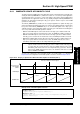
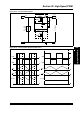
43.16.3 Multi-Phase PWM
The Multi-Phase PWM, illustrated in Figure 43-48, uses phase shift values in the PHASEx
registers to shift the PWM outputs with respect to the primary time base. Because the phase shift
values are added to the primary time base, the phase shifted outputs occur earlier than a PWM
signal that specifies zero phase shifts. In Multi-Phase mode, the specified phase shift is fixed by
the design of the application. Phase shift is available in all PWM modes that use the master time
base.
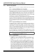
43.16.3.1 MULTI-PHASE BUCK REGULATOR
Multi-Phase PWM is often used in DC-to-DC converters that handle fast load current transients,
and need to meet smaller space requirements. A multi-phase converter is essentially a parallel
array of buck converters that are operated slightly out of phase with each other. The multiple
phases create an effective switching speed equal to the sum of the individual converters.
If a single phase is operating at a PWM frequency of 333 kHz, the effective switching frequency
for the circuit, illustrated in Figure 43-48, is 1 MHz. This high switching frequency greatly reduces
input and output capacitor size requirements. It also improves load transient response and ripple
figures.
Figure 43-48: Multi-Phase PWM
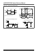
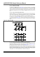
43.16.3.2 INTERLEAVED POWER FACTOR CORRECTION (IPFC)
Interleaving of multiple boost converters in PFC circuits is becoming very popular in the recent
applications. The typical interleaved PFC circuit configuration is illustrated in Figure 43-49. The
interleaved PFC operational waveforms is illustrated in Figure 43-50.
By staggering the channels at uniform intervals, multichannel interleaved PFC can reduce the
input current ripple significantly due to ripple cancellation effect. Smaller input current ripple
indicates low Differential Mode (DM) noise filter. It is generally believed that the reduced
differential mode noise magnitude makes the differential mode filter smaller. The output capacitor
voltage ripples are also reduced significantly as a function of the duty cycle.
+
PWM2H
PWM3H
L1
L2
L3
PWM1L
PWM2L
PWM3L
V
OUT
Multi-Phase DC/DC Converter
PWM1H
PWM1L
PWM2H
PWM2L
PWM3H
PWM3L
+VIN
PWM1H