
Specifications


© 2008-2012 Microchip Technology Inc. DS70323E-page 43-95
Section 43. High-Speed PWM
High-Speed PWM
43
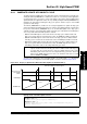
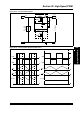
43.16.2 Push-Pull PWM Output Mode
The Push-Pull PWM Output mode, illustrated in Figure 43-47, alternately outputs the PWM signal
on one of two PWM pins. In this mode, complementary PWM output is not available. This mode
is useful in transformer-based power converter circuits that avoid flow of direct current that
saturates their cores. Push-Pull mode ensures that the duty cycle of the two phases is identical,
thereby yielding a net DC bias of zero.
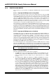
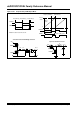
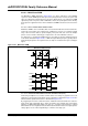
Figure 43-47: Push-Pull PWM Output Mode
T1
+
+V
IN
PWM1H
PWM1L
Push-Pull Converter
L1
V
OUT
PWM1H
PWM1L
DC
X - DTR
Period - DC
X + DTR
T
ON
TOFF
Period Period
Dead Time Dead Time Dead Time
Period
Duty Cycle
0
Period
Timer
Value
Timer Resets
PWMxH
Value
PWMxL
Duty Cycle
Duty Cycle Match
Half-Bridge Converter
+V
IN
+
T1
VOUT
PWM1H
PWM1L
+
L1
+
PWH1H
PWH1L
PWH1H
+V
IN
L1
V
OUT
Full-Bridge Converter
+
PWH1L
T1