
Specifications


dsPIC33F/PIC24H Family Reference Manual
DS70323E-page 43-90 © 2008-2012 Microchip Technology Inc.
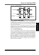
43.12.5 Asserting Outputs through Current-Limit
In response to a Current-Limit event, the CLDAT bits (IOCONx<3:2>) can be used to assert the
PWMxH and PWMxL outputs. Such behavior can be used as a current force feature in response
to an external current or voltage measurement that indicates a sudden sharp increase in the load
on the power-converter output. Forcing the PWM to an ON state can be considered a
feed-forward action that allows quick system response to unexpected load increases without
waiting for the digital control loop to respond.
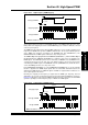
43.12.6 PENx (GPIO/PWM) Ownership
Most of the PWM output pins are normally multiplexed with other GPIO pins. When the Debugger
halts the device, the PWM pins will take the GPIO characteristics that is multiplexed on that pin.
For example, if the PWM1L and PWM1H pins are multiplexed with RE0 and RE1, the
configuration of GPIO pins will decide the PWM output status when halted by the Debugger.
Example 43-29: Code Example
Note: In Complementary PWM Output mode, the dead time generator remains active
under override condition. The output overrides and fault overrides generate control
signals used by the dead time unit to set the outputs as requested, including dead
time. Dead time insertion can be performed when the PWM channels are
overridden manually.
/* PWM output will be pulled to low when the device is halted by the
debugger */
TRISE = 0x0000; RE0 and RE1 configured for an output
LATE = 0x0000; RE0 and RE1 configured as Low output
/* PWM output will be pulled to high when the device is halted by the
debugger */
TRISE = 0x0000; RE0 and RE1 configured for an output
LATE = 0x0003; RE0 and RE1 configured as high output
/* PWM output will be in tristate when the device is halted by the debugger */
TRISE = 0x0003; RE0 and RE1 configured for an input