
Specifications


dsPIC33F/PIC24H Family Reference Manual
DS70323E-page 43-88 © 2008-2012 Microchip Technology Inc.
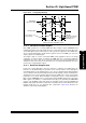
43.12 PWM OUTPUT PIN CONTROL
If the High-Speed PWM module is enabled, the priority of PWMxH/PWMxL pin ownership from
lowest to highest priority is as follows:
• PWM generator (lowest priority)
• Swap function
• PWM output override logic
• Current-limit override logic
• Fault override logic
• PEN
X (GPIO/PWM) ownership (highest priority)
If the High-Speed PWM module is disabled, the GPIO module controls the PWMx pins.
Example 43-25: PWM Output Pin Assignment
Example 43-26: PWM Output Pins State Selection
Example 43-27: Enabling the High-Speed PWM Module
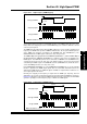
43.12.1 PWM Output Override Logic
The PWM output override feature is used to drive the individual PWM outputs to a desired state
based on system requirements. The output can be driven to both the active state as well as the
inactive state. The High-Speed PWM module override feature has the priority as assigned in the
list above. All control bits associated with the PWM output override function are contained in the
IOCONx register. If the PWMxH Output Pin Ownership bit, PENH (IOCONx<15>), and the
PWMxL Output Pin Ownership bit, PENL (IOCONx<14>) are set, the High-Speed PWM module
controls the PWMx output pins. The PWM Output Override bits allow the user-assigned
application to manually drive the PWM I/O pins to specified logic states, independent of the duty
cycle comparison units.
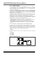
The State for PWMxH and PWMxL Pins if Override is Enabled bits, OVRDAT<1:0>
(IOCONx<7:6>), determine the state of the PWM I/O pins when a particular output is overridden
by the Override Enable for PWMxH Pin bit, OVRENH (IOCONx<9>) and the Override Enable for
PWMxL Pin bit, OVRENL bit (IOCONx<8>).
The OVRENH bit (IOCONx<9>) and the OVRENL bit (IOCONx<8>) are active-high control bits.
When these bits are set, the corresponding OVRDAT bit overrides the PWM output from the
PWM generator.
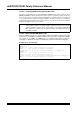
When the PWM is in Complementary PWM Output mode, the dead time generator is still active
with overrides. The output overrides and fault overrides generate control signals used by the
dead time unit to set the outputs as requested. Dead time insertion can be performed when the
PWM channels are overridden manually.
Note: When the PWM is configured for a resolution other than 1.04 ns (that is,
PTCON2<2:0> = 1, 2, 3, ... 7 or STCON2<2:0> = 1, 2, 3, ... 7), a NOP instruction
must be inserted between consecutive bit-writes to the OVRENH bit (IOCONx<9>)
and the OVRENL bit (IOCONx<8>).
/* PWM Output pin control assigned to PWM generator */
IOCON1bits.PENH = 1;
IOCON1bits.PENL = 1;
/* High and Low switches set to active-high state */
IOCON1bits.POLH = 0;
IOCON1bits.POLL = 0;
/* Enable High-Speed PWM module */
PTCONbits.PTEN = 1;