
Specifications


© 2008-2012 Microchip Technology Inc. DS70323E-page 43-87
Section 43. High-Speed PWM
High-Speed PWM
43
43.11.5.2 EXAMPLE 2: PIN SWAPPING WITH MOTOR CONTROL
The Motor Control example describes static swapping. Consider a generic motor control system,
that is capable of driving two different types of motors, such as DC motors and three-phase AC
induction motors.
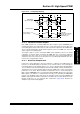
Brushed DC motors typically use a full-bridge transistor configuration, as illustrated in
Figure 43-44. The Q1 and Q4 transistors are driven with similar waveforms, while the Q2 and Q3
transistors are driven with the complementary waveforms. This is also known as “driving the
diagonals”. Note that the Q5 and Q6 transistors are not used in a brushed DC motor.
The transistors are configured as follows:
•Q1 = PWM1H
•Q2 = PWM1L
•Q3 = PWM2L
•Q4 = PWM2H
Figure 43-44: Motor Contro
l
When compared to the DC motor, an AC induction motor uses all the transistors in the full-bridge
configuration. However, the significant difference is that the transistors are now driven as three
half-bridges where the upper transistors are driven by the PWMxH outputs and the lower
transistors are driven by PWMxL outputs.
The transistors are configured as follows:
•Q1 = PWM1H
•Q2 = PWM1L
• Q3 = PWM2H (note the difference with DC motors)
• Q4 = PWM2L (note the difference with DC motors)
•Q5 = PWM3H
•Q6 = PWM3L
Example 43-24 shows the PWM pin swapping.
Example 43-24: PWM Pin Swapping
Q1
Q2
Q3
Q4
Full-Bridge Converter
Q5
Q6
+V
IN
+VIN
/* PWM Pin Swapping feature */
IOCONxbits.SWAP = 1;
/* PWMxH output signal is connected to the PWMxL pin and vice versa */