
Specifications


dsPIC33F/PIC24H Family Reference Manual
DS70323E-page 43-82 © 2008-2012 Microchip Technology Inc.
43.11 SPECIAL FEATURES
The following special features are available in the High-Speed PWM module:
• Leading-Edge Blanking (LEB)
• Individual time base capture
• PWM pin swapping
• PWM output pin control and override
• PWM immediate update
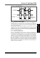
43.11.1 Leading-Edge Blanking (LEB)
Each PWM generator supports LEB of the current-limit and fault inputs through the LEB<6:0>
bits (LEBCONx<9:3>) and the PHR (LEBCONx<15>), PHF (LEBCONx<14>),
PLR (LEBCONx<13>), PLF (LEBCONx<12>, FLTLEBEN (LEBCONx<11>) and
CLLEBEN (LEBCONx<10>) bits in the Leading-Edge Blanking Control registers. The purpose
of LEB is to mask the transients that occur on the application printed circuit board when the
power transistors are turned ON and OFF.
The LEB<6:0> bits (LEBCONx<9:3>) are edge-sensitive, and support the blanking (ignoring) of
the current-limit and fault inputs for a period of 0 ns to 1057 ns in 8.32 ns increments following
any specified rising or falling edge of the PWMxH and PWMxL signals.
Equation 43-8: LEB Calculation for Devices without Remappable I/O
Equation 43-9: LEB Calculation for Devices with Remappable I/O
In High-Speed Switching applications, switches (such as MOSFETs/IGBTs) typically generate
very large transients. These transients can cause problematic measurement errors. The LEB
function enables the user-assigned application to ignore the expected transients caused by the
MOSFETs/IGBTs switching that occurs near the edges of the PWM output signals.
The PHR bit (LEBCONx<15>), PHF bit (LEBCONx<14>), PLR bit (LEBCONx<13>) and PLF
bit (LEBCONx<12>) select the edge type of the PWMxH and PWMxL signals, which starts the
blanking timer. If a new selected edge triggers the LEB timer while the timer is still active from a
previously selected PWM edge, the timer reinitializes and continues counting.
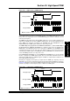
The FLTLEBEN bit (LEBCONx<11>) and the CLLEBEN bit (LEBCONx<10>) enable the
application of the blanking period to the selected
fault and current-limit inputs. Figure 43-39
illustrates how an application ignores the fault signal in the specified blanking period.
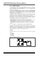
On devices with the LEB Version 2 register, it is possible to specify periods of time where the
current-limit and/or Fault signal is entirely ignored. The BCH, BCL, BPHH, BPHL, BPLH and
BPLL bits in the LEBCONx register select the PWMxH, PWMxL and/or CHOP clock signals as
the source of the state blanking function. It is also possible to blank the selected Fault or
current-limit signal when the PWMxH output is high and/or low, and if the PWMxL is high and/or
low. The PWM State Blank Source Select bits (BLANKSEL<3:0>) in the PWM Auxiliary Control
register (AUXCONx<11:8>) select the PWM generator used as the blanking signal source.
Note: Refer to the “High-Speed PWM” chapter in the specific device data sheet to
determine the LEB version that is available for your device.
LEB Duration @ Maximum Clock Rate = (LEBDLYx<8:0>) * 8.32 ns
LEB Duration @ Maximum Clock Rate = (LEBCONx<6:0>) * 8.32 ns