
Specifications


dsPIC33F/PIC24H Family Reference Manual
DS70323E-page 43-80 © 2008-2012 Microchip Technology Inc.
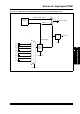
The analog comparator provides high-speed operation with a typical delay of 20 ns. The positive
input of the comparator is connected to an analog multiplexer (INSEL<1:0>) in the CMPCONx
register. The positive input of the comparator measures the current signal (voltage signal).
The negative input of the comparator is always connected to the DAC circuit. For more
information, refer to Figure 45-1 in Section 45. “High-Speed Analog Comparator” (DS70296).
The typical DAC settling time is 650 ns. The DAC settling time is measured when Range = 1 (high
range) and CMREF<9:0> transitions from 0x1FF to 0x300. Each analog comparator has a
dedicated 10-bit DAC that is used to program the comparator threshold voltage.
The DAC range can be selected using ‘RANGE’ in the Comparator Control register (CMPCONx).
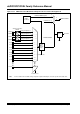
The dsPIC33F “GS” series devices with remappable I/O support four virtual RPn pins (RP32,
RP33, RP34 and RP35) that are identical in functionality to all other RPn pins, with the exception
of pinouts. Refer to the “I/O Ports” chapter in the specific device data sheet for more information.
These pins provide a simple way for inter-peripheral connection without utilizing a physical pin.
For example, the output of the analog comparator can be connected to RP32 and the PWM Fault
Source (FLT1) can also be configured for RP32. The virtual pin configuration is shown
in Example 43-22.
Example 43-22: Virtual Pin Configuration for Devices with Remappable I/O
43.10.8 Current-Limit Interrupts
The state of the PWM current-limit conditions is available on the CLSTAT bit (PWMCONx<14>).
The CLSTAT bits display the current-limit IRQ flag if the CLIEN bit (PWMCONx<11>) is set. If
current-limit interrupts are not enabled, the CLSTAT bits display the status of the selected
current-limit inputs in positive logic format. When the current-limit input pin associated with a
PWM generator is not used, these pins can be used as general purpose I/O or interrupt input
pins.
The current-limit pins are normally active-high. If set to ‘1’, the CLPOL bit (FCLCONx<9>) inverts
the selected current-limit input signal and drives the signal into active-low state.
The interrupts generated by the selected current-limit signals are combined to create a single
IRQ signal. This signal is sent to the interrupt controller, which has its own interrupt vector,
interrupt flag bit, interrupt enable bit and interrupt priority bits associated with it.
The fault pins are also readable through the port I/O logic when the High-Speed PWM module is
enabled. This capability allows the user-assigned application to poll the state of the fault pins in
software.
43.10.9 Simultaneous PWM Faults and Current-Limits
The current-limit override function, if enabled and active, forces the PWMxH and PWMxL pins to
read the values specified by the CLDAT<1:0> bits (IOCONx<3:2>), unless the Fault function is
enabled and active. If the selected fault input is active, the PWMxH and PWMxL outputs read the
values specified by the FLTDAT<1:0> bits (IOCONx<5:4>).
RPINR29bits.FLT1R = 0b100000; /* Fault Source(FLT1) connected to RP32 */
RPOR16bits.RP32R = 0b100111; /* Output of the analog computer 1 connected
to RP32 */